Start a New Photogrammetry
The setup process is very simple and it does not require any specific knowledge.
To start a photogrammetry, select Tools ▸ Photogrammetry. HighDesign switches to the Photogrammetry workspace, with the Photogrammetry setup window, a gray background and a limited set of drawing tools:
- Arrow;
- Construction objects;
- Lines;
- Poly-lines with straight segments;
- Hatches;
- Curves;
- Viewing tools (Panning, Zoom and Measure).
STEP 1: select the image
Push the “Choose…” button and select the image file to open. Supported file types are: TIFF, PNG, JPEG.
_
Press the “Next” button: the image is now displayed on screen and the Photogrammetry setup window changes.
STEP 2: define the internal geometry
Once the image is open, select the geometric type of the object in the picture. There are two possible options, based on the visible geometry and camera angle:
- All three directions X, Y and Z are visible in the image: there are at least two horizontal lines, two vertical and two for the depth;
- Two directions X, Y are visible. The image shows at least two horizontal lines and two vertical, but no depth line is visible; this type includes pictures taken with the lens parallel to the surface and scans of plans.
When you choose the geometry type, a grid is added to the image on the drawing area. Adjust the grid to match the shape of the object in the picture.
Click the handles of the grid on its vertices and move them until they match the horizontal and vertical cue lines that are visible in the picture. Windows, side walls, sills, jambs of doors and windows and frames are all useful elements.
If the geometry shows two sides of the object, a second grid serves for the reconstruction of the third direction. Drag the two blue depth lines by their endpoints to match the depth cue lines on the picture. You can adjust the grid and the depth lines keeping in mind that usually lines far from the center of the picture have a deformation depending on the quality and focal length of the used lens.
_
- The focal length value is optional.
Push “Next” button to go to the next step of setup.
STEP 3: define the known measures
Two lines, one green vertical and one red horizontal, are displayed over the picture. These lines, drawn in the perspectival view corresponding with the internal geometry of the picture, will be utilized to enter the two known measures.
- Drag the vertical line over the known dimension, in this case the jamb of the arched door, and stretch/shorten it by the endpoints till it matches the known object: enter the known vertical measure in the corresponding field of the setup floating window and select the drawing units.
- Drag the horizontal line over the known object, the sill of the door, adjust it till it matches the known dimension and enter the actual measure in the corresponding field and set the drawing scale of the projection.
_
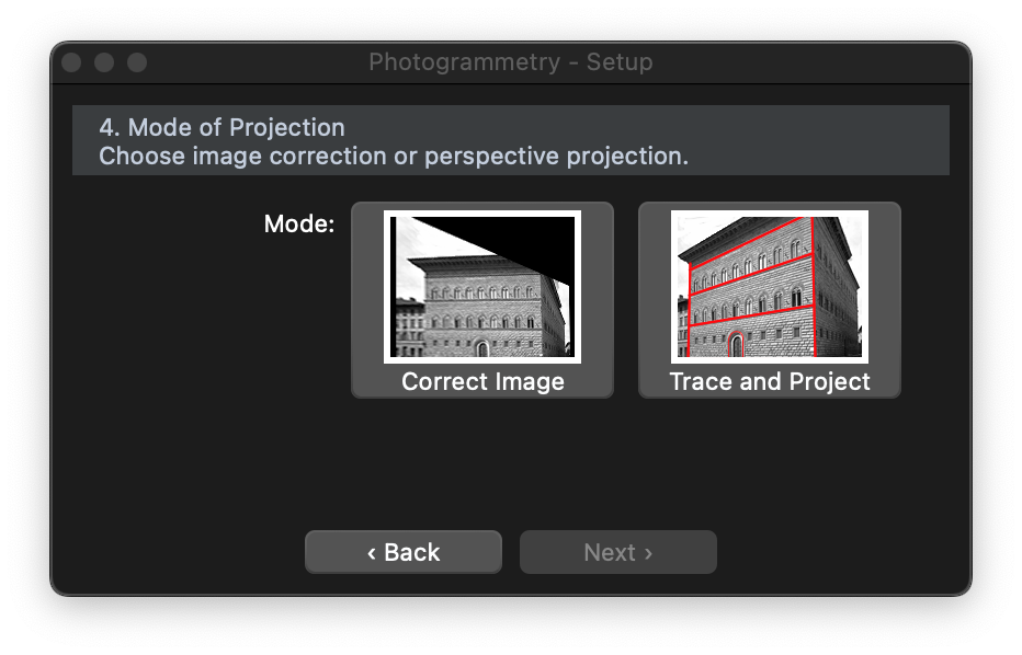
STEP 4: choose projection mode
The setup is now complete and it is possible to choose the mode of projection between image deformation and vector projection. By choosing the image deformation the image will be stretched to correct the perspective deformation and match the given proportions: the resulting image then could have to be resized to fit the known measures.
The second option, “Trace and Project”, consists in tracing all the objects of the image you wish to survey to get the projection at the desired drawing scale.
 _
_