Subsections of Drawing
Basic Drafting Skills
The basic process of drawing any object in HighDesign consists of selecting the desired tool, choosing a drawing method from those available in the tool and clicking on the drawing area to start the construction of the object. If there are selected objects, the first click deselects everything.
New objects are created using the current default graphic attributes and properties: layer, stroke and fill, line-type, etc. If the object being created is an element, that is, an object that is more complex than a basic shape such as hatches or texts, you can set the specific defaults via its Settings window. Double-click the tool icon on the toolbox to open the Settings window for that class of objects.
Attributes and properties can also be changed at any time after the object has been created: select the object and change the desired properties.
Drawing Techniques
The default drawing procedure adopted in HighDesign is “Click-Move-Click,” i.e. to draw a line you click to set the start point, move the pointer to the desired location and click again to set its end point. Click-drag is also supported. You can change the drawing method in Preferences ▸ Drawing.
To cancel an operation you can hit the “Esc” button on the keyboard, or press the right mouse button.
Multi-segment objects, such as polylines, hatches, paths, follow the same general method: click to define the vertices, double-click or press the Esc key to end.
The general drafting procedures described above are also valid for Drafting, Documentation and Design tools.
Reference Objects
The Reference Objects tool can be used to mark reference elements and auxiliary objects in the drawing. It has three methods:
- point, to create reference points in the drawing.
- construction line, to add infinite lines for alignments and margins.
- origin, to set the origin of the coordinate system in the current drawing.
By default, reference objects are not displayed on printed outputs and PDF documents.
Topics in this Section
Subsections of Reference Objects
Construction Lines
Construction lines (also referred to as guides) are infinite lines that serve as references in the drawing for positioning and alignment.
Construction lines can be created with two methods:
Construction line from rulers
When the rulers are visible in the main drawing area (View ▸ Show Rulers), click and drag on the horizontal or vertical ruler to place an aligned guide. You can snap to drawing objects while dragging to place the guide at the desired location. This method works with any drawing tool.
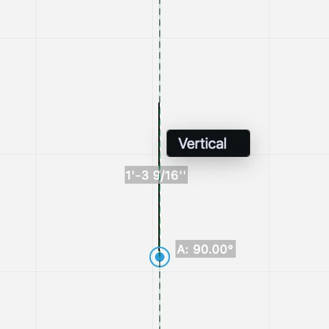
Construction line by point
With this method you can create a guide oriented at an arbitrary angle.
- Activate the Alignment Objects tool > Guides method.
- Click to set the center and define the direction with the pointer. You can enter a definite angle by pressing the A key on the keyboard or clicking an existing linear object to draw a parallel construction line. To set the distance of the construction line from the reference linear object, press the L key on the keyboard, enter the value and click on the desired location.
You can create a guide parallel to an existing guide, like a duplicate: with the Guides method, click on an unselected guides in the drawing and move. Use the keyboard to enter a constrained distance.
Editing a Construction Line
Guides can be moved just like any other object: select the line, click anywhere on it and move the pointer. To constrain the translation by a definite distance, enter the desired length directly and press Return or Enter.
Drawing Origin
This tool changes the origin of cartesian axes and rulers. The coordinates of the drawing and dimensions are updated automatically. You can also change the Origin by using the button on the intersection of the rulers. In HighDesign SE and Pro each sheet has its own Origin.
Points
Points are simple reference points on the plane that are used to mark positions and help align objects in the drawing. Points can be added by using the Alignment Objects tool and are created by some editing tools to mark locations.
To place a point, activate the Reference Objects tool > Point method and click anywhere on the drawing area.
To move a point, select it, click its handle and move the pointer.
Lines
The Line tool lets you draw simple 2D lines of any length and angle. The tool includes four methods and allows editing of selected lines.
Topics in this Section
Subsections of Lines
Double Lines
Creates two parallel segments of the same length at the specified offset from each other. Activate the field next to the method icons to enter a value.
Double lines can be traced from the axis or from one side.
The standard method of drawing a line of given length is to set the first point, push the L key (or the corresponding shortcut), enter the value and push the Return key. The same procedure applies to Angle (A), X, Y. More methods are described in the Basic Tasks chapter.
Editing a Line
Line objects can be edited in the same way with the Arrow tool or the Line tool.
To stretch a line:
- Select the line.
- Click one of its end points.
- Move the pointer. Hold down the Shift key to keep the original angle.
- Click to end the operation.
To move a line:
Line by Center
To create a line from its center:
- Click to specify the center or middle point of the line.
- Move the pointer in the desired direction and by the desired distance. Note that as you move the pointer, you actually define one half of the line so when entering a length value you define the length of half line.
- Click again to specify the end point.
Line by Start Point
This method lets you create a line from a start point to and end point.
To draw a line:
- Click to specify the start point.
- Move the pointer in the desired direction and by the desired distance.
- Click to specify the end point.
Length and angle constraints are available during the construction of lines.
Segmented Lines
Creates a series of segmented lines connected on their end point. Note that this method creates a series of independent lines. To create a composite object made of multiple segments, use the Polyline tool.
To create segmented lines:
- Click to set the first vertex.
- Move the pointer.
- Click to set the next vertex.
- To end the series, double-click on the last vertex.
Polygons
Use this tool to draw closed polygonal shapes, like rectangles, squares and regular polygons of any number of sides.
Polygons include two object classes, Rectangle and Polygon, that have specific editing rules.
Topics in this Section
Subsections of Polygons
Rectangles
The Polygons tool provides three methods to create rectangles: rectangle by vertex, rotated rectangle by vertex, and rectangle by center.
Rectangle by Vertex
To draw a rectangle, click to set the first vertex, move the pointer and click again to set opposite vertex. You can add diagonals to a rectangle by pressing the Option key on the second click. To draw a square, use the rectangle tool and hold the Shift key to constrain the diagonal direction.
To set the size of the rectangle, click to set the starting vertex, then push the “W” key to set the width and “H” to set the height. Positive values go rightwards and upwards. To edit the rectangle with either the Arrow tool or the Drawing tool active, click on vertices to resize, on midpoints of sides to stretch, and click on sides or center point to move.
Rotated Rectangle
Click to place the first vertex, move the pointer and click again to set the base angle; then move the pointer and click a third time to set the height of the shape. To set the dimensions, click the first vertex, push the “A” key to set the angle, the “W” key for the width and the “H” key for the height.
Rectangle by Center
Click to set the center of the rectangle; move and click to define the orientation and the first axis; move and click again to define the perpendicular axis.
Editing a Rectangle
You can modify a rectangle by stretching one of its four vertices, the mid-points of the sides, or move it by the center.
- Select the rectangle. Depending on the handle point you click, you can stretch, resize or move the object.
- Vertex: resize the rectangle by one of its vertices or corners. You can enter the new dimensions by pressing the W and H keys as you resize the shape.
- Middle points: stretch the rectangle and modify its width or height by clicking the middle point of one of the sides.
- Center: move the rectangle to a new location.
Regular Polygons
The Polygons tool includes three methods to create regular polygons of a variable number of sides: polygon by external radius, polygon by internal radius, and polygon by side.
To define the number of sides, use the input field on the Properties bar.
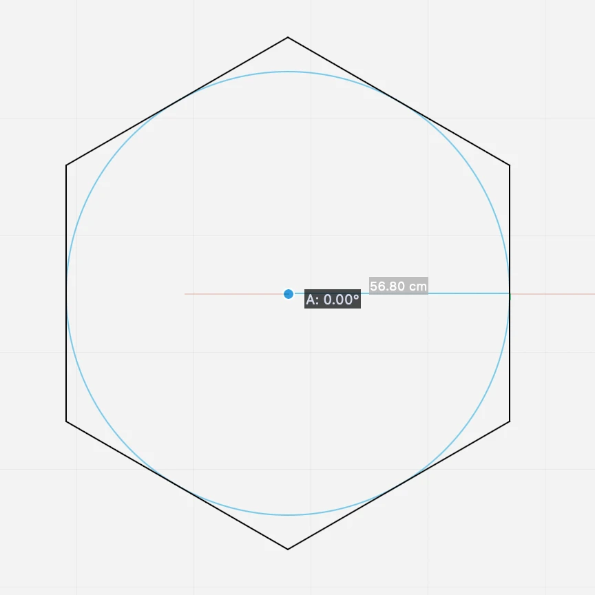
Regular Polygon by External Radius
This method allows you to draw regular polygons with any number of sides starting from three. To set the desired number of sides, use the offset field in the Methods bar next to the tool methods and insert the value.
To draw a Regular Polygon by the external radius, click to set the center of the shape (all these regular polygons are inscribed in a circle), move the pointer and click again to set the radius of the circle circumscribed and the vertex of the polygon.
Regular Polygon by Internal Radius
This method lets you draw the polygon by setting the center and the radius of the circle inscribed in the polygon.
Regular Polygon by Side
Creates a polygon defined by the side. To create the polygon, draw the first side, exactly like a line of the desired length and angle, and click again to place the shape at the desired location.
Arcs, Circles and Ellipses
Use this tool to draw circles, arcs, ellipses and arcs of ellipse. All the methods for circular arcs can be used to draw full circles by clicking the switch that appears on the screen next to the first point of the arc, or by holding down the Alt key.
The construction can be both graphical, via clicks on the drawing, or numerical via the keyboard input.
Topics in this Section
Subsections of Arcs, Circles and Ellipses
Arcs and Circles
Use the Arcs, Circles and Ellipses tool to create circles and circular arcs. The tool includes methods to create arcs and circles by a number of conditions and points.
Each method provides an on-screen button to let you choose to create an arc or a circle.
_
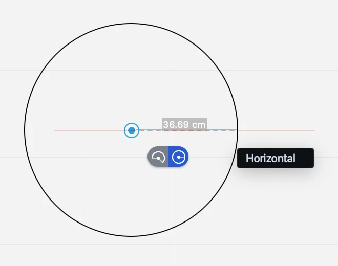
Arc/Circle by Center and Radius
To draw an arc or circle click to set the center (or set it with by coordinates), then select the arc or circle option on the on screen floating button.
To draw an arc, set the radius by pressing the L key, set the start angle by pressing the A key and set the end angle by pressing A again. To draw an arc graphically, move the pointer and click again to set the start angle; with the next click you define the end angle of the arc.
To draw a full circle, set the length of the radius by pressing the L key on the keyboard and the start angle / end angle by pressing the A key. Press Return to confirm.
Arc/Circle by Diameter
Click to set the first vertex of the diameter, move the pointer and click again to set the second vertex. You can define the diameter by pressing the L key, and the angle by pressing the A key.
Arc/Circle by Start Point, End Point, Radius
Click to set the start point and end point of the arc and click to set the radius. The two points and the radius can also be defined via numeric input using the X, Y and Dx, Dy coordinates and L value. Hold the “alt” key to switch the direction of the arc.
Arc/Circle by Three Points
Click to set the points that define the arc. The three points can also be defined via numeric input using the X, Y coordinates or L and A values.
Arc/Circle by Tangent
Click on the endpoint of a line or on the endpoint of an arc to set the first point of the arc drawn by the tangent to that object at that datum endpoint.
Ellipses
Ellipse by Bounding Box
Set the start point, move and define the end point of the diagonal. The ellipse is inscribed in the rectangle defined by its diagonal.
Ellipse by Center and Radii
Click to set the center of the ellipse, move and click to define its first radius; move again and click to set its second radius. The center can also be defined by using the X, Y coordinates and the radii can be defined by pressing the L key during their construction.
Quarter of Ellipse
This method allows you to draw quarters of ellipse by clicking on its two vertices.
Polylines
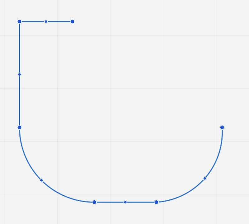
The Poly-line tool creates a polygonal shape made of a connected series of straight and curved segments. Curved segments are arcs drawn by center or by tangent.
The polyline object offers some advantages over individual elements, such as the ability to modify a point without having to rebuild the sequence, or grab a segment by its mid-point to stretch the shape. Also, since a polyline is one object, its perimeter and area are always available and up-to date.
Topics in this Section
Subsections of Polylines
Create a Polyline
To draw a poly-line, click to set the first vertex, move the pointer and click to set the next vertex. Double-click to end the sequence.
When you construct a polyline, an action icon follows the start point of each segment. Click it or hover on it to open the options menu and choose the type of the next segment, delete the last segment or end the shape. To close the poly-line, select the corresponding option or place the last vertex on the first one.
_
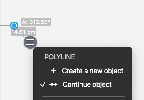
Continue an Existing Polyline
To extend an existing open polyline, so as to add new vertices at one end, you can use the Continue option.
 _
_
To continue an open polyline:
- With the existing polyline unselected, click on one of its endpoints. The pop-up options menu button appears next to the clicked vertex.
- Open the options menu and choose Continue object.
Modifying a Polyline
A polyline can be edited in several ways: activate the Polyline tool and select the object (if it is not already selected); then:
- click a vertex to stretch it
- click a mid point to move the entire segment
- click on a segment to add a vertex
- place a vertex over another vertex to delete it
- hover the cursor on a vertex to open the Edit menu and add or delete the vertex.
_
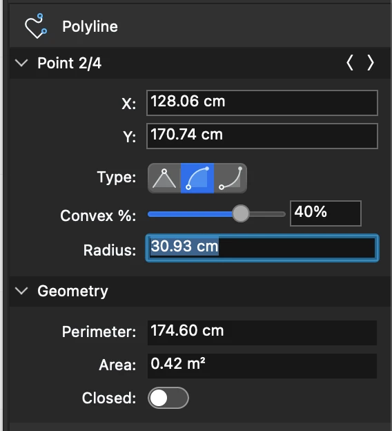
The Object info panel provides more editing options:
- Change the type of the current vertex. Use the left/right arrows on the Point header to select the current vertex, then choose one of the following types:
- Straight segment
- Convex arc
- Concave arc
 _
_
Curves
The Curves tool allows you to draw, single and multiple Bézier curves, Freehand lines, Spline curves and clouds.
Topics in this Section
Subsections of Curves
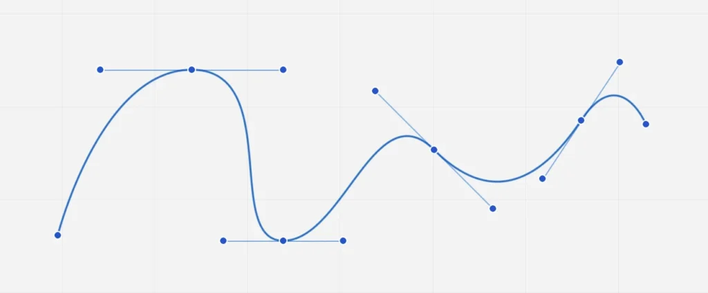
Bézier Curves
This method can be used to draw multiple, connected Bézier paths, parametric curves defined by two vertices and two tangent lines:
- Click to set the first vertex, move the pointer and click to set the next vertex; double click to end the chain of Bezier curves.
- To draw a curve during construction, click and drag to define its profile.
The resulting path now can now be edited to smooth the vertices and turn the straight segments into the desired curves: this way the first tangent of the next curve is always defined by the previous one. Bézier curves have the Fill property: select the desired color on the “Fill color” menu of the Properties bar.
Edit a Bézier curve
- Hover the cursor over one vertex of the selected curve toshow the pop-up menu with the options to add or delete vertices and smooth or sharpen the path by creating connected curves or straight segments.
- By clicking on one of the four control points of a selected curve, you can change its position and visually adjust the profile. With multiple Bézier curves, by editing a definition point the connected tangents are constrained to keep the same angle: move the control points of the tangents to change the angle and adjust the shape of the curve.
- Hold down the Alt key while moving the control points of the tangents to edit asymmetrically; Alt key + Cmd key to disconnect the tangents.
_
The nodes of a bézier path can also be modified through the Object Info panel: select the node and change its coordinates and node type. The node types are:
- Straight: the node has no tangents and the curve is rendered as a straight line.
- Symmetric: the tangents extend by the same length and angle on both sides of the node.
- Asymmetric: the tangents are aligned at the same angle, but different length.
- Disconnected: the tangents are totally independent and each control point has its own angle and length.
 _
_
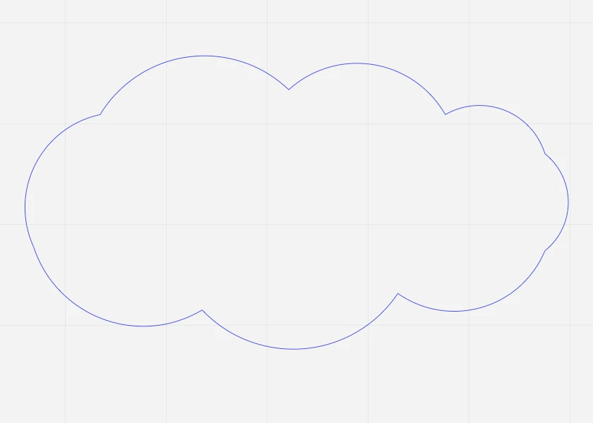
Clouds
Use this method to draw revision clouds and mark areas of the drawing that require special attention or further development.
The Revision Cloud method creates a composite shape made of arcs.
 _
_
Freehand Lines
The Freehand method lets you create spline curves by following the movement of the cursor. The algorithm transforms the movement of the cursor on screen to smooth curves.
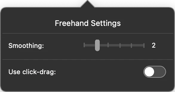
The freehand method has two properties: smoothing factor, that defines the complexity of the curve, and the drawing option. You can adjust the smoothing factor of new paths through the Freehand settings window: 1 means that the path will preserve its original shape, but might have many vertices; 6 is the maximum smoothing and the path will be considerably simplified.
 _
_
On the same panel, you can also choose to draw freehand paths with a click-drag method instead of the standard click-click: this option is specially useful when used with a pen tablet, because it allows a more natural way of drawing.
Splines
A spline is a smooth curve that passes through a series of points. Splines in HighDesign are third-degree (cubic) polynomial segments, known as nonuniform rational B-Splines (NURBS).
Splines have a wide range of uses due to the simplicity of their construction, ease of editing and adaptability to mimic complex shapes.
Construct a Spline
To construct a spline, click to specify the start point, move the pointer and click to specify the next point. Double-click to end the curve or return to the start point to close the shape.
Press the X (cancel) button or the Esc key to cancel the last point.
_
Editing a Spline
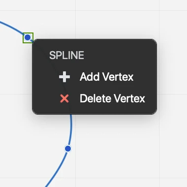
You can modify the profile of a spline by stretching a point, or by adding and removing vertices.
- Hover the cursor over one vertex of the selected curve to show the pop-up menu with the options to add or delete points;
- Move the given points of the selected curve with the Arrow tool or with the pointer and the Spline or Freehand tool method active.
 _
_
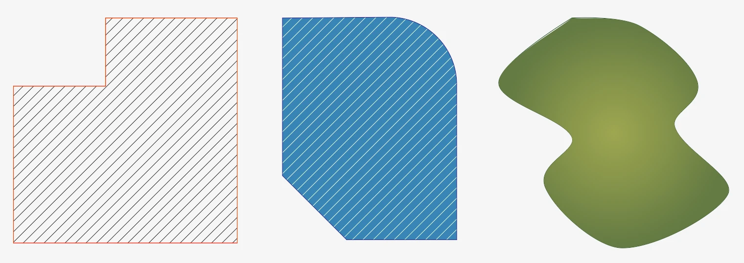
Hatches and Fills
Use the Hatch tool to fill existing objects or regions with vector hatch patterns, solid color fills, gradients, or textures. You can also use a combination of different filling modes, such as hatch and solid color.
You can select a predefined hatch pattern or create your own (SE/Pro): HighDesign comes with a wide range of built-in hatches that can be easily extended with your own hatches.
Hatches and fills are elements that include various parameters that can be set and modified in the Hatch tool settings panel.
Topics in this Section
Subsections of Hatches and Fills
Create Polygonal Hatches
To draw a polygonal hatch
- Click to specify the start point.
- Move the cursor and click to specify the next vertices.
- Double-click or click the start point to end the operation close the region.
 _
_
You can click the X (Cancel) button next to each new vertex or press Esc to cancel the last vertex in the sequence.
You can press the Return key to confirm a vertex, or double-press Return to close the shape.
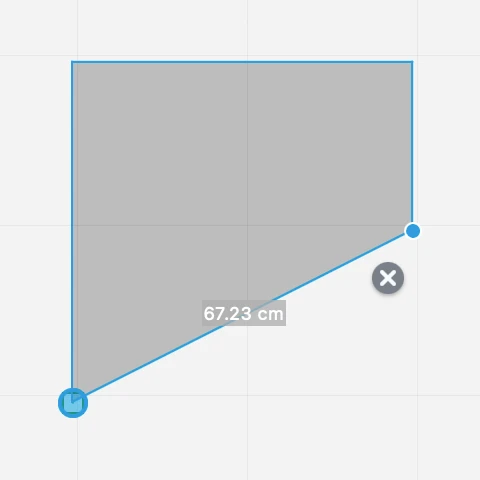
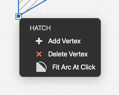
Editing a Hatch
Hatch and fill regions can be edited by adding and removing vertices, stretching a vertex, or by fitting a segment to an arc. Most operations can be performed by clicking a vertex or a side of the shape, or by opening the Edit popup menu.
To Open the Edit Menu
With the hatch selected, move the pointer over a vertex and wait half a second until the Edit menu opens next to the vertex.
 _
_
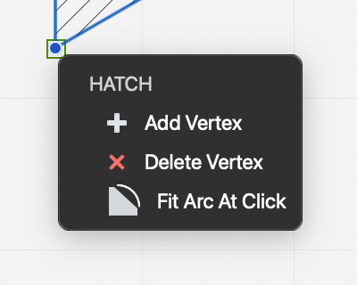
Add and Remove Vertices
To add a vertex to a selected hatch
- Click on the border on any segment. The cursor changes to show that you are about to add a point.
- Alternatively, open the Edit popup menu over a vertex and choose Add Vertex.
To remove a vertex
- Open the Edit popup menu and choose Delete Vertex.
Fit Arc at Click
Hatch regions support only straight segments, but can be applied to arcs with a specific command available on the tool popup menu. To apply a hatch to an arc, do the following:
- Create the hatch by clicking the vertices of the outline. While defining the hatch boundary, do not follow the profile of the arc with the hatch points. Instead, add the chord of the arc between its start and end points.
- Select the hatch you just created, move the pointer over one of the points at the start or end point of the arc and hover for half a second. The options popup menu opens.
- Select Fit Arc at Click and click on the arc.
Hatch at Click
Use this method to apply the current hatch to shapes defined by lines, poly-lines, polygons, arcs, curves and other graphic objects: click inside the shape to fill it automatically with a Hatch object. The shape must be made of objects of any of the supported classes and connected at their end points.
Object classes supported by the Hatch at Click method:
- Lines
- Poly-lines
- Rectangles and regular polygons
- Arcs, Circles, Ellipses
- Bezier paths and splines
- Walls
With the exclusion of walls, the other objects can be combined together to form the base shape. For example, you can apply the hatch to a shape made of lines and arcs, or lines and a spline. Move the pointer over the shape to see the preview of the boundary of the hatch that is going to be created.
If you want to ignore the automatic boundary defined by walls and use another shape instead, hold the Alt key down. This will force the tool to ignore the region defined by the walls and look for any other region enclosing the click point.
The new hatch or fill is created with current default properties defined in the Hatch Settings panel. As with other objects, you can select it at any time and change its properties.
The hatch is automatically inserted behind the boundary shape, so that its Z position is immediately below the lowest object of the boundary. Hold the Shift key down to insert it on top of the shape.
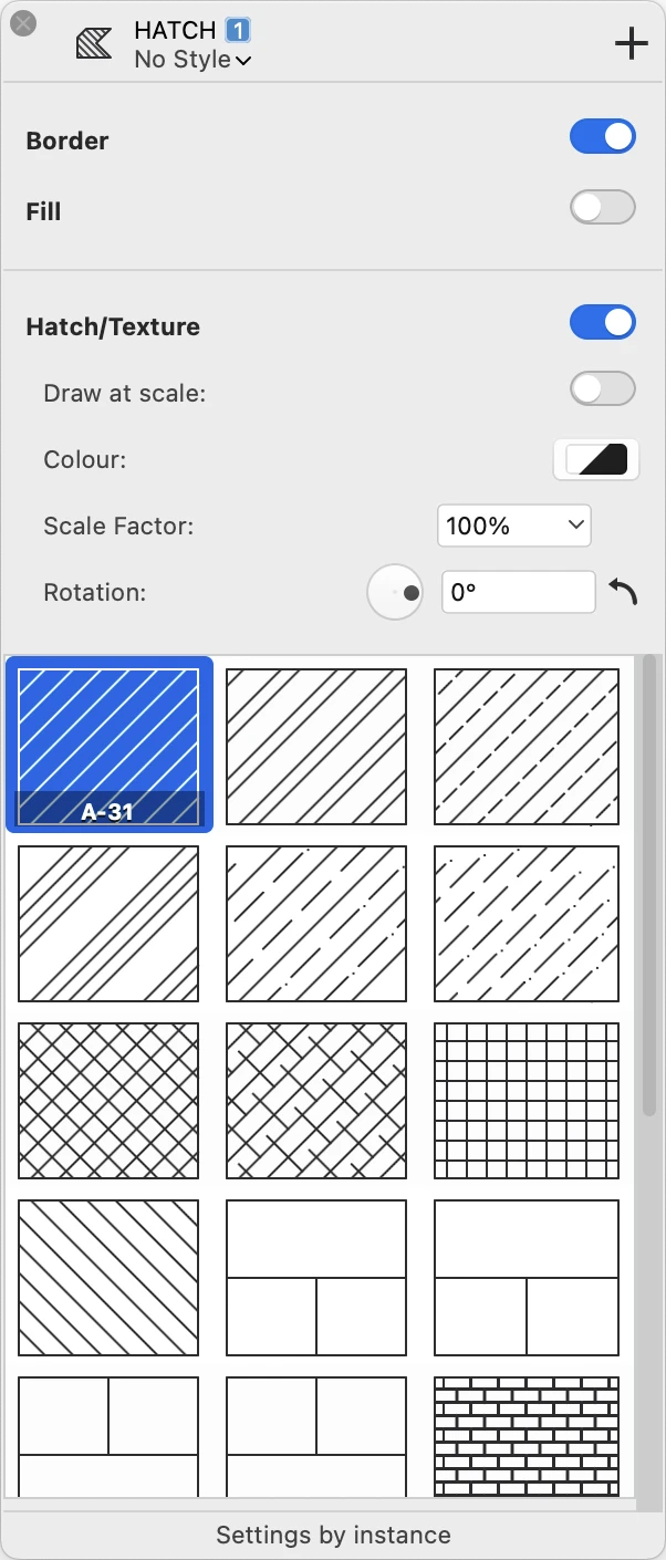
Hatch Tool Settings
Specify the various parameters of new and existing hatch regions by using the Hatch tool settings window. Select Edit ▸ Settings Window ▸ Hatch Pattern or double-click the corresponding icon on the Toolbox to open the Hatches & Fill Settings window.
 _
_
Borders and Fill
Use the Border and Fill switches to enable or disable the display of the region’s border and color fill. To set or change the fill color, use the Fill button on the Properties bar or Graphic Attributes panel.
Hatch and Texture
Use the Hatch/Texture switch to enable or disable the display of a hatch pattern or texture fill. Hatch patterns and textures include the following options:
- Draw at scale. Enable this option to have the vector hatch displayed at the current sheet scale. This option is not available for textures.
- Color. Use the Color button to specify the pen color of the hatch pattern.
- Scale Factor: change the scaling factor of the hatch pattern. This value is not connected to the drawing scale factor and ranges from a minimum of 1% to a maximum of 1600%.
- Rotation: change the orientation of the hatch by defining a rotation angle.
Select the hatch type or texture from the list.
The last cell of the Hatches table is a special button: click it to add hatch types to the current project. This option opens the “Hatch patterns” pane of the Resource Manager window.
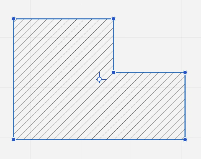
Opening Islands Inside a Hatch
Hatch and fill regions can have multiple islands, or holes, inside the region. You can open a island with the polygonal or circular island methods, or with the Hatch at Click method.
Polygonal Island
Select this method to create polygonal openings in existing hatches by drawing the shapes of the islands within the selection. To do this, just activate the Hatches & Fills tool, select the method and click on the vertices of the polygonal opening you wish to create within the hatch. This method can be used on either selected and unselected hatches. The nearest hatch is detected automatically as you move the cursor over the project.
Circular Island
This method allows you to open circular islands defined by center and radius. Click to set the center and click again to set the radius: it is also possible to set the value of the radius numerically.
To edit the island, select the hatch and locate the pointer over one vertex of the opening till the tool menu shows up giving you the options to remove the island, to delete one vertex or to add another one.
Opening islands with the Hatch at Click method
The Hatch at Click method can be used to open islands (holes) inside a hatch: select the hatch and click on one or more shapes inside its boundary. Only the edited hatch object must be selected.
Images
Images in HighDesign are external references, that is objects that are inserted into the drawing and keep a reference to the original file so that they can be reloaded if needed. Images are treated like objects that you can insert, move and manipulate together with the other drawing objects.
Images can be inserted via the Insert Image command, available on the File or Project ▸ Insert menus. The supported file types are TIFF, JPG, PNG, GIF, WebP, TGA and PDF. Alpha levels present in TIFF, PNG and WebP files are preserved. Once inserted into the project, the image is treated as a vector object with coordinates, width, height and angle parameters.
Topics in this Section
Subsections of Images
Editing Images
Images can be edited graphically or by their parameters.
To edit an image graphically:
- Select the image, then
- Click the center handle to move the image
- Click one of the corner handles to resize the image.
- Click one of the middle handles on the sides to resize the image in that direction.
As you resize an image, its horizontal and vertical resolution values change to reflect the new pixel/display size ratio.
To restore the original image size and resolution, open the Image tool settings window and push the Restore Original Values button.
To edit an image by its parameters:
- Select the image, then
- Open the image tool settings panel and change width, height and resolution.
- Alternatively, use the Object Info panel to resize and rotate the picture.
Image Tool Settings
Use the Image settings window to select new images to insert, and set the default size, resolution, transparency and storage format of image objects.
The Image tool settings window contains a preview of the image and several sections that show the current values and parameters.
_
Preview and Image Info
This area allows you to choose an image to insert or replace, and shows a preview of the image at the current transparency.
When no image is currently selected, the Preview area shows an Open Image button. Press that button to open a pop-up dialog from which you can select one of the images already inserted in the project, a recently-opened image, or choose an image file from your computer.
_
When an image object is selected in the drawing, you can replace the image by pressing the Replace Image button that appears when you move the pointer over the preview. Replaced images preserve size, resolution and transparency of the previous image.
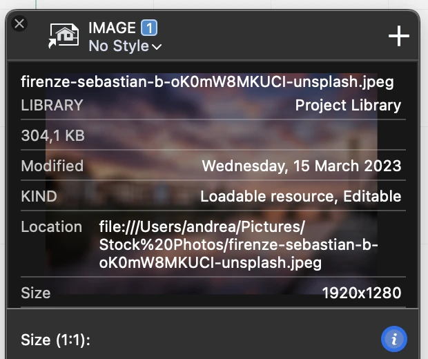
Press the Info button to view details and information about the image and its original file. The information include the location of the image file, its file size and modification date, and its bitmap size in pixels.
 _
_
Size and Resolution
Use the width, height and resolution fields to resize the image. To constrain a proportional resizing, press the constrain proportions button, and open the units pop-up menu to select the preferred units.
Images can be displayed at their print resolution or at screen resolution. Use the Display at screen resolution switch to change this parameter. The visible size of the image is larger at lower resolutions.
To restore the original dimensions of the selected image after it has been resized, push the Restore Original Values button.
Transparency
Images can be displayed at variable transparency, ranging from 0% (fully visible) to 100% (fully transparent). This setting does not modify the image and can be adjusted at any time.
Storage Format
Images are handled like other vector objects and saved in the project file. The internal format can either be PNG, which preserves the full quality of the image, or JPEG, which compresses the image and saves file size considerably, but reduces the quality. JPG is very good for photographic images, but not for images that contain line drawings, such as city maps or scanned drawings.
Insert an Image
HighDesign lets you easily add pictures to your project from several graphic formats (TIFF, JPEG, PNG, GIF, BMP, TGA, WebP, PDF). Images inserted into the project keep their resolution and are displayed at the real print size: it is possible to handle them as any other vector entity. PNG, TIFF and WebP images are imported with their alpha channel if present.
You can insert a picture in your project in several ways:
- File ▸ Insert Image…
- Project ▸ Insert ▸ Image…
- Double click the Image tool icon to open the Settings pane, push the Open Image button and the Open button on the pop-up panel.
- Drag and drop an image file from the computer onto the drawing area.
- Drag and drop a picture from another application, such as a web browser or a photo archiving software.
- Paste a picture from the system clipboard.
Images are inserted by their lower-left corner.
PDF documents can be inserted as high-resolution images. When you choose a PDF document with the Insert Image command, you are presented with a dialog where in you can select the page to import, if more than one, and set the resolution at which the image object will be created.
Symbols
The Symbols Tool is a drawing tool which allows you to put in your project entire drawings or portions of drawings already created and stored in a library with just one click. Using Symbols is a convenient way for reproducing many times the same group of elements with independent rotation, mirroring and scale factors.
Symbols can store attributes, which are information displayed at the desired location of the current view.
To edit or set the Symbol Tool properties, select Edit ▸ Settings Window ▸ Symbol or double-click the Symbol Tool icon in the Drawing Tools bar.
Topics in this Section
Subsections of Symbols
Choose and Insert a Symbol
Use the Symbol tool settings window to select the symbol to insert.
- The table lists the currently selected library folder: this folder may contain many sub folders and can be organized at your choice. Browse through this table to select the symbol file.
- Once a symbol has been selected, a lists all of its views shows up if available: select a view from the list to activate it; double-click its name to change it and click on the pencil icon to edit the symbol/ view (for custom symbols only).
Insert a Symbol into the drawing
- Open the Symbol Library dialog by choosing Edit ▸ Settings Window ▸ Symbol or by double- clicking the Symbol icon in the Drawing toolbar;
- Select a symbol in the Folders table and choose one of the available views;
- Set its size and optional parameters;
- Review or change the default attributes if available;
- Click one of the defined insertion points, the center or one of the vertices or midpoints of the thumbnail to select the current insertion point;
- Either drag the preview to the drawing or click on the desired point of the drawing.
To create a new symbol, to add a view to a symbol or to edit an existing symbol, are also available the specific commands on the Project menu.
Create and Edit Symbols
The “New Symbol” and the “Edit Symbol” functions, also available through the Project menu, when activated switch to a different workspace with a limited set of tools: in this environment you can draw, modify and save symbols and symbol views.
You can either create a new symbol from scratch or create a new symbol from the selection: in this case you can also activate this function through the Radial Menu for a quicker workflow. This way the selected objects are now visible in the “Edit Symbol” environment whereas all the other elements of the drawing are hidden.
Create a new symbol:
- Select “New Symbol” on the Project menu;
- The Environment turns to the “Edit Symbol” context with a limited set of tools and the “New Symbol” dialog opens; this dialog is divided into four sections:
- Symbol Name;
- View;
- Attributes;
- Insertion Points;
- Draw the symbol;
- Type the symbol name;
- Select the destination folder through the folder button;
- Use the “+” button to add a new view;
- Type the view name;
- Set the attributes;
- Insert the attributes in the drawing of the symbol view;
- Place the Insertion Points on the desired locations of the symbol view;
- Press the “Save” button on the dialog.
Attributes of the Symbol
Attributes are information added to the current view of the symbol: these information are defined by an ID, a Prompt, showing on screen, and a Default value which will be displayed in the project.
The Attributes section of the New Symbol dialog shows:
- The menu of the existing attributes of the view (visible when editing a symbol and its attributes);
- The Add button to create a new attribute;
- The button to remove the selected attributes,
- The “Edit attribute” button to modify the currently selected attribute.
Since attributes are a sub-class of text, they can get text properties such as font, font size, alignment, style and rotation angle: the “Define Attribute” window displays all these information and options.
To insert the attribute, just click on the desired location of the symbol view.
Edit a Symbol
To edit a symbol you can click on the Edit button of the selected symbol on the Settings window, or select the symbol on the drawing and either choose “Edit Symbol” on the Project menu or use the Radial Menu.
The “Edit Symbol” workspace opens and you can modify the symbol, add views to the symbol by pushing the “+” button of the dialog or delete views through the “-” button, change the attributes of the view.
By pushing the “Save” button, the environment turns back to “Drawing”. Changes made to a symbol are immediately visible in all the symbol duplicates of the drawing.
Symbol Tool Settings
Use the symbol tool settings window to select the symbol to insert, specify its insertion point, dimensions and display options, and enter any associated attributes.
The Symbol settings dialog has two panes: Symbol and Attributes. The Symbol pane provides you with many options to choose a new symbol and set its graphic properties.
_
Selecting a Symbol
Use the library browser to select a symbol either for insertion or to replace a selected instance.
You can select a symbol to insert by any of the three available libraries. Push the library selector buttons to view the items contained in the default HighDesign library, in your User library, or among the symbols already used in the project.
You have two display options to select a symbol: grid view and list view. Use the selector buttons on the right of the symbol browser header to change the view.
**Select a Symbol in Grid View **
In grid view, you can view the previews of the symbols in the current folder. Double-click a folder to enter it and use the pop-up menu above the symbol browser to go back to a previous folder.
Some symbols may have more than one view. To select a view, open the popup menu next to the symbol name and select one of the available views.
_
Select a Symbol in List View
The list view is very similar to the list view of a desktop operating system: click the disclosure triangle or double click a folder to open it, and select the items in the list. Similarly, open the disclosure triangle of a symbol to list its views.
_
Set Instance Parameters
When you select a symbol, its preview is visible on the top side of the panel along with its default dimensions, angle and options.
_
To select an insertion point
- Move the pointer over the preview, the insertion points appear around the bounding box of the symbol.
- Click a point.
- Any custom insertion point will also be visible and selectable in addition to the nine default locations.
To specify width, height and angle
Enter the desired sizes in the width and height fields. To constrain a proportional resize, click the “chain” symbol between the two fields.
To change the units or to restore the dimensions to their original values, open the popup menu in the Height field and select the desired command.
To lock a symbol instance dimensions and prevent it from being resized by scale changes or editing commands, push the Lock button. When a symbol instance is size-locked, it will keep the entered size until unlocked or resized via the Width and Height fields.
Use the angle field and slider to change the symbol’s orientation, or push the Vertical and Horizontal Mirror buttons to flip the instance around its internal vertical or horizontal axes.
Scaling and Color Options
You can have a symbol be displayed at the correct size at any drawing scale. This is particularly useful for example with architectural symbols, furniture, or trees. To enable this feature, push the Draw at Scale button.
To force the symbol to draw its fills with the same color as the background, or use its original stroke colors, push the Colors button to open the pop-up window.
_
Command Buttons
Use the command buttons placed below the symbol browser to create a new folder in the User library, create a new symbol by the selected objects in the drawing area, duplicate a symbol, or delete a symbol.
These commands are only enabled when the conditions are met for each command.
Symbol Attributes
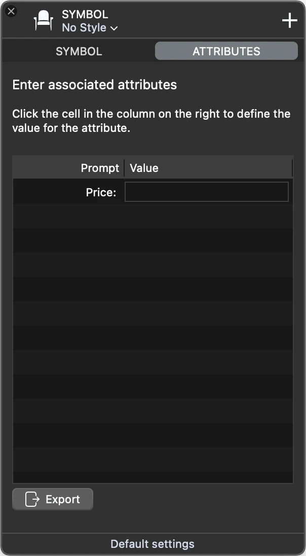
The Attributes pane displays the editable, non-visible attributes of the current view. Use this pane to set the values of the attributes of the symbol or symbol view you are inserting in the project or to change the values of the current selection.
If the symbol contains no editable attributes, the list on this panel is empty.
This panel only lists attributes that are not visible in the drawing.
 _
_
Groups
HighDesign provides the ability of grouping different objects together as a single item. Most editing operations and transformations can only be applied to selected items, either to individual objects or to a group of objects at once.
Groups are a convenient way of organizing items by binding heterogeneous items in one “collection” which behaves as one object. Once a number of drawing objects are grouped together you can select them simply by clicking any of the group members. By default, the grouped objects retain their attributes, such as color, line type, weight, etc. Changing the attributes of a group applies the changes to all its members.
Topics in this Section
Subsections of Groups
Edit Groups
Grouped objects can be edited all together like a single drawing object by stretching the handles of the bounding box of the group with the Arrow tool. A group can be moved, rotated, mirrored or scaled like any other object.
- A group can be resized and moved with the Arrow tool. Properties applied to a group are applied to all the group members.
- To select individual members of a group, hold down the command key and click the object. The object will be selected and available to to be modified or deleted. This method is more suitable for quick editing operations.
- You can also modify the members of a group through the Edit Group command.
The Edit Group workspace
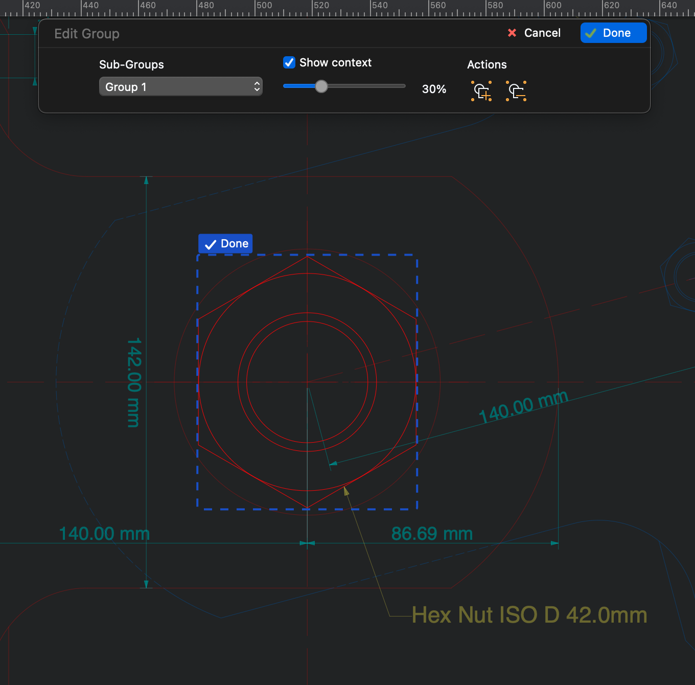
You can activate the Edit Group workspace by selecting a group and clicking the Edit icon on the top-left handle point or by choosing** Project ▸ Edit Group…** This workspace opens a panel with specific commands that let you manage sub-groups, show or hide the context, add objects to the group or remove objects from it.
 _
_
If the group includes sub-groups, you can use the Sub-Groups menu to activate any sub-group or return to the main group. To edit a sub-group, click the Edit icon above its top-left corner. Click “Done” to end the edit.
By default, the edited group is displayed within its context, that is, the surrounding objects of the drawing it is inserted into. You can adjust the level of opacity of the context or disable it altogether.
To add an existing object to the group, push the Add Object button in the Actions section and click any object in the context. In likewise manner, push the Remove Object and click on any object of the group to remove it from the group. The removed object will be moved to the sheet where its original group resides.
You can also draw any class of object using the tools that are available on the Toolbox. Any object created in this way will be added to the current group.
Push Done to confirm the changes and return to the normal workspace, or push Cancel to dismiss all the changes made in the Edit Group workspace.
Group Commands
All commands connected with groups area available in the Project menu. The functions to manage groups are Group, Ungroup, Automatic Grouping, Ungroup All, Edit Group.
- “Group” creates a new group with all the currently selected items;
- “Ungroup” breaks the selected groups;
- “Add to Group” includes selected objects in the currently selected group;
- “Automatic Grouping” is an option that automatically creates groups with items of a shape, i.e. rectangles, regular polygons, poly-lines, walls, etc.;
- “Ungroup All” breaks all groups, including those not selected.
- “Edit Group” opens a workspace where you can modify the selected group by editing, adding or removing members by using the normal drawing tools.