Subsections of Get Started
Create a New Project
You can create a new HighDesign project in two ways, from the Home window or from the Menu Bar, and you can choose to create a model using default settings, or to create a model starting from a template (Pro).
To create a project using default settings
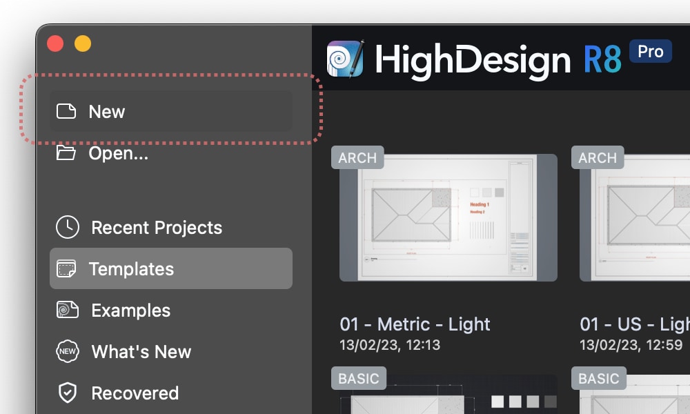
From the Home window, click New.
Alternatively, you can create a new project using the menu bar: select File > New…
The new project is created with the current settings of units, paper size, and colors. You can then use the Project Settings window to adjust the project to your needs.
To create a project using a template (Pro)
In HighDesign Pro, you can create a new project starting from a predefined template. In the Home window, select Templates from the side bar and choose the desired template. The default templates include variants for the metric and imperial systems. The default templates are organized by discipline, architecture, structural, and mechanical/engineering (MEP) , and each template include layers and settings that are specialized for the target discipline.
The default templates usually include a sample drawing that showcases the settings of pens and colors. When you start a new drawing using a template, you can delete everything (Cmd-A or Ctrl-A and Delete) and start your own drawing.
The Templates panels also shows your custom templates after the default ones.
Introduction to HighDesign
About HighDesign
HighDesign is a design and documentation tool for architects and design professionals working in the Architecture, Engineering and Construction (AEC) industry. With a modern, intuitive interface and powerful drafting and design functions HighDesign combines computer-aided-design (CAD) features with advanced building-oriented tools.
The wide range of drafting, design and documentation functions and the sophisticated features of project organization allow the rapid production of concepts, drafts and designs.
A project in HighDesign is a complete presentation of drawings, views, details, information, images and layouts that will assist the user in the design workflow from the conceptual to the design and production phases.
Fundamentals
A project in HighDesign is a set of drawings, symbols, views, details and documentation elements such as annotations, tags, dimensions and non graphic information. It is very important that all these items are organized in categories with a defined hierarchy.
The objects of the project are logically grouped through Layers and organized as separate drawings contained in Project Sheets. Project Sheets have their own drawing scale and units.
Project Elements and Object Hierarchy
Each item of the project has its hierarchy which allows to easily structure and organize the different parts of the drawings. Therefore we have generic and specific objects of the project.
The hierarchy of the items of the project classifies them as:
- Objects - any item of the project. It can be a line, a text, a wall, an image a title block, etc.
- Graphic Objects - 2D drafting objects and shapes such as lines, polygons, circles, curves.
- Elements - graphic objects with advanced settings (hatches, symbols, texts, annotations, dimensions).
- Building Elements - parametric components of the building such as walls, columns, doors, windows.
Objects, Graphic Objects, Elements and Building Elements are organized in Classes, usually corresponding to the tool options used to draw them: Line, Arc, Wall, Door are different classes of objects.
Classes of objects can have sub-categories called Families: e.g. swinging door and sliding door are different families of the door class.
The objects of the project can have abstract definitions of their parameters: Basic Styles, Graphic Styles (for the elements of the project) and Building Element Types (for the building elements).
Compare Editions
HighDesign is available in three different licenses to best suit your needs: LT, Standard and a Pro version.
HighDesign LT is the light-weight, accessible CAD solution for everyone who needs the precision and power of a full CAD software, without the complexity of more design-oriented features and tools. HighDesign LT supports the DXF and DWG file format (Model data only).
HighDesign SE is a CAD program designed to provide the user all the most used drawing and editing tools. This version is intended for home and small office users who will benefit from its powerful functions, ease of use and tight integration with the operating system. HighDesign Standard supports the DXF and DWG file formats.
HighDesign Pro includes all the features of the Standard version, plus many others designed to increase personal productivity and satisfy the advanced needs of professional users such as architects and civil engineers. HighDesign Pro adds sets of design tools such as walls, columns, doors, windows geared for a professional, intensive use.
Installing
HighDesign Trial Version
When you download HighDesign from the Ilexsoft website, the software launches as a time-limited trial version.
The limitations in the Trial version are:
- Operative for 30 days of use;
- Printed pages and exported images have a “HighDesign Trial” watermark;
HighDesign Trial lets you explore all the available features, including those of the Pro version such as walls, sheets, views, photogrammetry, etc.. At the end of the trial period, the application will no longer launch.
When you purchase a license, launch HighDesign and insert your Owner name and License Key into the License dialog. There is no need to download a separate package.
Install on Mac
The download version is a compressed Disk Image file (.dmg). Depending on your Internet preferences, the file could have already been expanded after the download.
Once the file has been expanded, you should see on your Desktop (or your default download location) the “HighDesign” dmg file. Double-click it to mount the drive.
To install HighDesign, drag the icon to a folder on your local or network disk. There is no required location; however, if you have multiple users on your computer, put it in the main Applications folder to make it accessible to all of them. Note that you will be required to log in as an administrator to write to the Applications folder.
Activate HighDesign and Remove the License on Mac
- Launch HighDesign, click the Activate button on the first screen or go to HighDesign > License Information…
- Enter name and license key exactly as they appear in the HighDesign Activation email sent from Ilexsoft.
Upgrade keys must be registered for the same name used in the previous license.
To remove the license, go to HighDesign > About HighDesign and click on the License button: select the license in the table, click the Delete button and confirm.
Uninstall on Mac
- Quit HighDesign.
- Open a Finder window.
- Delete the HighDesign folder from the main library:
- On the left pane of the Finder window, click your user name.
- Hold down the Option (Alt) button on your keyboard, click Go in the menubar, then select the Library option in the drop-down list.
- Open the Application Support folder.
- In the Application Support folder, find the Ilexsoft HighDesign folder, and then drag it to the trash.
- Delete the HighDesign application:
- On the left pane of the Finder window, click your user name.
- Hold down the Option (Alt) button on your keyboard, click Go in the menubar, then select the Library option in the drop-down list.
- In the Preferences folder, drag the following file to the trash: com.ilexsoft.HighDesign.plist
Install on Windows
After downloading the file, follow these steps to install HighDesign:
- Log in to the computer with a user account that has administrator rights;
- Double-click the EXE install file. You can also context-click and select Run As an Administrator;
- Click Next in the Welcome dialog box;
- Click on the “I accept the terms of this license agreement” button in the End User License Agreement if you agree to the terms;
- Click the Next button to install HighDesign in the default location;
- Click the Install button if you’re satisfied with the settings;
- Click the Finish button when prompted;
- Launch HighDesign.
Activate HighDesign and Remove the License on Windows
Launch HighDesign, go to Help > Activate License… and enter name and license key exactly as they appear in the HighDesign Activation email sent from Ilexsoft.
Upgrade keys must be registered for the same name used in the previous license.
To remove the license, go to Help > About HighDesign and click on the License button: select the license in the table, click the Delete button and confirm.
Uninstall on Windows
To uninstall HighDesign, go to the Start menu (the windows logo) and follow the path below:
Select Settings > Apps > Apps & Features > HighDesign; Click the “Uninstall” button.
Opening Files
To open files in HighDesign, click the Open button from the Home window or choose File ▸ Open… from the menu bar. Use the system Open dialog to select the desired file.
The Open command can open both HighDesign project files and DXF/DWG drawings. On Windows, you can use the default “All available types” filter or restrict the visible files by selecting a type-specific filter.
IMPORTANT: HighDesign project files are not backwards compatible. When you create or modify a project using the current release of the software, you cannot open the project later using a previous release.
- When you open a file that was created in a higher-level edition of HighDesign, for example a Pro document in HighDesign LT, a dialog informs you that the project was created in a different edition and that saving the changes will modify the project.
The project you open in HighDesign sets all its internal settings, such as units, default sizes, background and selection colors, etc.
Saving Files
HighDesign provides several ways of saving a file:
- Save
- Save As
- Save Special
Save
The Save command lets you save on disk the current project; if the project does not have a name, a standard save dialog is shown on the screen.
Save As
Performs the same function as Save, but forces the display of the standard Save dialog that allows you to define a location for the file and enter a file name.
Important: If the current project was already saved or if it was opened from an existing file, Save As creates a copy of the project file and replaces it as the current file. Any subsequent changes and save commands will update the file created by the Save As command.
Save Special
The Save Special menu includes the following commands:
- Selection as new document Saves the currently selected objects as a new document. It is only enabled when there are selected items in the current project.
- Sheet as new document Saves the currently active sheet as new document. Only available in HighDesign editions that include drawing sheets.
- Visible Sheets Saves all visible drawing sheets as a new document that preserves the sheet structure of the current document. Only available in HighDesign editions that include drawing sheets.
- Previous HighDesign Project Version Lets you save the current project in a format compatible with a previous version of HighDesign.
- Template In HighDesign editions that support Templates, this command stores a copy of the current document as a custom project template. Templates save every setting and drawing item of the project in the current state.
Tip
When you enter a file or template name in the Save As dialog, you can add a prefix enclosed by square brackets, such as [A01]. The prefix will be read as a badge over the project preview in the Home Window.
User Interface
Topics in this section
Subsections of User Interface
The Home Window
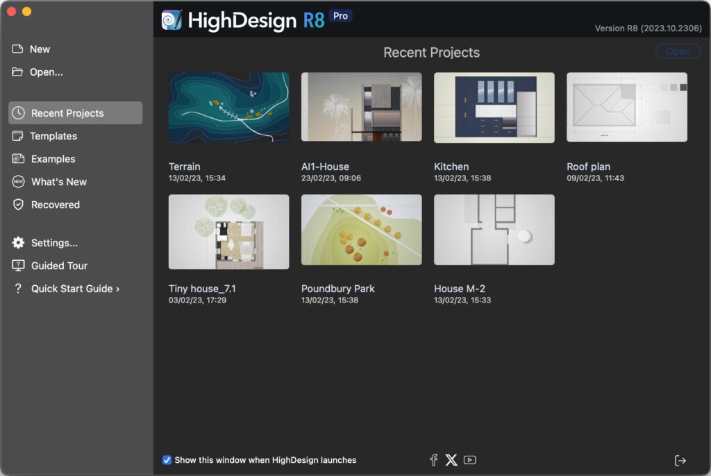
The Home window opens by default when you launch HighDesign and presents the options to create or open projects, choose a template, and contains links to useful resources. It is organized in several sections that can be accessed through the sidebar on the left. From top to down:
- New: creates a new, empty project. New projects use the settings of the last active project as a base. Colors, units and basic project options are set automatically.
- Open: opens the default Open File dialog to open a HighDesign (.DSN) file or AutoCAD drawing (.DXF, .DWG).
- Recent projects: browse a list of recently-opened projects. Only .DSN projects are listed. Select a file and click the Open button or double-click to open it.
- Templates (Pro): this section contains the built-in and user templates.
- Examples: open an example to explore the features and the possibilities of HighDesign.
- What’s New: shows a summary of the new features in the current version.
- Recovered: this section lists any auto-saved files that may be detected when the application launches. If you need to open a recovered file, select it from the list and press the Open button. Important: note that auto-saved files are not retained after the application quits, so any recovered file that is not opened and saved when detected will be lost.You can access the Recovered section at any time during the session.
- Settings: opens the Application Settings window.
- Guided Tour: starts a tour of the user interface of the main Project window. A popover panel explains the functions of each area of the Project Window. Use the “Next” and “Back” buttons of the popover window or the arrows of the keyboard to browse through the different elements of the main window.
- Quick Start Guide: opens the web page of the HighDesign Quick Start.
 _
_
The Home window also allows to open .DSN project files, templates and .DXF/.DWG drawings by drag-and-drop: drop the file over the window to open it.
**TIP: **The Home window supports file name tags in the form of [text]. Any text between two square brackets appears as a badge on the top-left corner of the thumbnail.
The Project Window
The main functions of HighDesign are visible and ready to use in the Project Window and in the surrounding toolbars and Sidebar.
The project window as it appears on a new document._
- The Drawing Area in the middle of the project window displays the project views and the sheets used to draw and edit drafting objects and project elements.
- The toolbars provide essential functions, such as the drawing tools, the drawing methods, the input fields and commands, the edit functions, and the properties controls. Through these commands, arranged in logical areas, all the drawing functions are easily accessible.
- The Sidebar provides functions that are mainly used to organize the project and manage project elements: the Project Browser and the Views panels, the Object Info and the Project Styles panels.
- The Menu bar on the top of the project window displays the menus listing almost all of the program functions, commands and features.
Toolbox
- Selection: select project elements by direct click or by selection area; modify selected elements
- Sketch: create and modify 2D drawing elements.
- Documentation: insert and modify texts, dimensions, text notes, tags, and define detail areas (standard/pro) and add temporary measurements.
- Design: create and modify architectural elements like walls, openings, columns (Pro).
- View: change the position of the drawing in the canvas via the panning function, the level of zoom; by preferences these tools can also be grouped in a dock and displayed on one side of the drawing area.
Main Toolbar
Placed on the top margin of the drawing area, the main toolbar bar lets you quickly access the most common functions used to modify the drawing with just one click on the icon. The buttons are contextually enabled when the conditions for the use of the tool are met, like number and type of selected items.
Note that this toolbar does not show all the available functions, but only the most commonly accessed. More functions and commands are available on the Drawing and Tools menus.
_
Geometric Transformations:
Main Toolbar
Placed on the top margin of the drawing area, the main toolbar bar lets you quickly access the most common functions used to modify the drawing with just one click on the icon. The buttons are contextually enabled when the conditions for the use of the tool are met, like number and type of selected items.
Note that this toolbar does not show all the available functions, but only the most commonly accessed. More functions and commands are available on the Drawing and Tools menus.
 _
_
Geometric Transformations:
- Move
- Duplicate
- Multiply / Distribute items along a line
- Multiply / Distribute items on a circular arc
- Rotate
- Angle of Rotation
- Mirror
- Mirror & Duplicate
- Stretch
- Scale drawing
Object Editing:
Composite Tools:
Composite Tools:
- Fillet two lines with an arc
- Chamfer two lines with a straight segment
- Offset, to create concentric copies of the clicked objects at a given distance
- Extrude, to create a copy of the selected objects with projection lines
- Explode, to convert the selected items into their base components
- Convert to Poly-line
- Apply Hatch
- Calculate Area
- Find Center of Mass
- Fit Text box
Methods Bar
The Methods Bar displays the construction methods and available options of the current tool, e.g. Line from one endpoint or from its midpoint, or arc by center, by diameter, by three points, etc. This bar is contextual and changes its contents according to the selected project tool and can include an additional input field to quickly insert a parameter value.
Properties Bar
The Properties bar is located at the top of the main window, just above the horizontal ruler and below the Edit Bar. You can use it to quickly set the graphical properties of the drawing items and change those of the selected one.
From left to right: Layer; Pen color; Fill color, gradient and transparency; Line-type; Start and end markers; Pen weight; Settings Window button (active when compatible items are selected); Copy and Paste Properties buttons.
Input Bar
Placed on the bottom of the drawing area the Input Bar provides all the controls to set the drawing constraints, geometric conditions and input of coordinates, lengths and angles.
From left to right:
- The menu to activate the snap options.
- The buttons to set the parallel, orthogonal and intersection constraints.
- The menu to change the drawing units and the drawing scale of the current sheet.
- Input fields: X, Y coordinates, length and angle. When drawing an item, the coordinates change from absolute to relative coordinates dX and dY. You can switch between absolute and relative coordinates by clicking the X and Y icons.
- The utility buttons and menus, to set the zoom level and the display mode of pen weights.
NOTE: Depending on the available screen size, the appearance and contents of the Input bar can change. At smaller resolutions, the Snaps menu includes the constraint functions, and the zoom menu includes the Zoom to Fit, Zoom In, Zoom Out and Zoom Previous commands. The input fields are always visible.
Side Bar and Utility Panels
**Customize the Side Bar **(Pro)
In HighDesign Pro the Side bar can be customized by using the commands on the Window menu:
- Minimize Side Bar
- Panels:
- Show as Floating Windows;
- Show in Side Bar;
- Restore Defaults;
- List of all available panels or floating windows.
Panes of the Side Bar and Utility panels
By default in HighDesign Pro the panes displayed in the Side Bar are Project Browser, Project Views, Object Info and Project Styles and Types. With other editions of HighDesign the configuration of the Side Bar is different.
Project Browser (SE-Pro)
The Project Browser pane lists all the project sheets: drafting sheets, detail sheets and layouts.
Use this pane to manage and organize sheets and to browse the different components of the project. This pane is not available in HighDesign LT.
Project Views (SE-Pro)
The Views pane shows a list of all the saved project views (available in HighDesign Pro only).
Layers
The Layers pane shows the layers used in the project and provides the functions to manage them.
Object Info
The Object Info pane allows to view and edit coordinates and geometric parameters of the selection. It also allows the setup of the current sheet and to add information.
Graphic Attributes
This pane provides in one handy array the graphic features of project elements, including stroke and fill attributes: it also provides the Shadow section for a complete setup of the shadow property of elements.
Overview/Zoom
The Overview utility pane displays a real-time 2x magnification of the sector of the current pointer location on the drawing area; if the mouse pointer enters the thumbnail, an overview of the entire drawing is displayed and it is possible to centre the view of the project with a click.
Snaps
This pane provides all the snap options and the main drawing constraints.
Arrange
The Arrange panel displays the buttons for all the Arrange Order, Align and Distribute objects commands.
Project Styles and Types (Pro)
In HighDesign Pro use this pane to view, browse and manage graphic styles and element types of the current project.
Photogrammetry Preview (Pro)
This is a live preview of the projection of the current photogrammetry (Pro only).
Rulers
Placed on the left and top of the main window, rulers help drawing and placing objects in a layout with accuracy. Rulers show the current position of the pointer and the bounds of the selected objects and are dynamically linked to the current measurement unit, drawing scale and zoom factor.
- The button located on the top-right hand corner between the two rulers lets you place the new origin: click it, move the orthogonal guides appearing on screen and click to set the new location.
- On the right end of the top horizontal ruler, a button opens a pop-up menu which lets you select a new measurement unit or open the “Units” pane of the Preferences window.
- You can add a horizontal or vertical guide by clicking on a ruler and dragging the pointer on the drawing area.
The Object Info Panel
The Object Info panel provides easy access to coordinates and other geometric parameters, as well as textual information on selected objects. If no graphic object is selected, the Object Info panel provides all information relating to the current sheet.
This panel lets you read and edit the coordinates of any of the object’s control points: width, height, length, angle, etc.
_
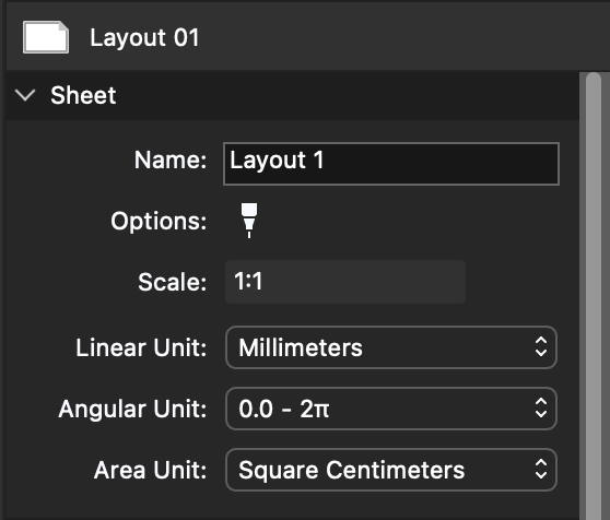
The Object Info panel is the main interface for configuring the current sheet, detail or layout: the various sections of the panel provide all the controls and fields needed to define name, scale, units, page size, graphic options and other information.
Info Object panel sections
The panel is organized into distinct sections that group together affine data and vary according to the item displayed:
Sheet :
When no object is selected, object information displays information on the current sheet.
_
- Header : sheet class
- Sheet : name, options, scale and units
- Paper size : visible for sheets that support one paper size.
- Class-specific settings
Object of the project :
Header
The header section of the panel displays the icon and class of the current element.
Header
The header section of the panel displays the icon and class of the current element.
- When you select one or more objects in the drawing, Object Info immediately displays all the numerical properties of the last object selected. The icon and name of the current object are displayed in the top bar of the window, as are the back and forward arrows used to scroll through the objects in the selection. ;
- Some objects, such as symbols, texts, dimensions or walls, have special parameters which are not displayed in the Object Info panel: when one of these objects is selected, its parameter window can be opened by clicking on the icon in the top bar of the Object Info panel, or by clicking on the Show parameters button in the ID section;
By default, Object Info modifies all selected objects of the same type. To modify only the current object, whose values are displayed on the panel, open the header context menu and choose “Apply only to current object”. This option remains selected until it is changed again.
For multiple selections, use the Previous and Next buttons on the right to activate the current object.
Point
The Point section displays the X, Y and Z coordinates of the current point. The current point is highlighted in the drawing, and you can use the “Previous” and “Next” buttons to scroll through the object’s handles. To modify a value, click on the field, insert the new value and press the Return key on the keyboard.
 _
_
- Depending on the type of object and the active point, the action resulting from editing the coordinates of the active point may be a stretch or a translation. For example, if you edit point 2 of a line, it is stretched; if you edit point 3 of a circle (its center), the action is a translation. ;
- When a rectangle or polygon is selected, this section indicates the type of transformation compatible with the current active point. With poly-lines, it is possible to modify the convexity of the segment described by the active point.
Geometry
The Geometry section displays values describing the object’s size and orientation, such as width, height, radius, length, angle and so on. Fields such as width and height can be connected to constrain the object’s proportions.
This section also displays read-only values calculated on the basis of the current coordinates and size, such as perimeter and area.
Some objects, such as dimensions and measurement paths, only display their value in a read-only field, as their size depends on other objects. Walls add controls that allow you to quickly modify the construction.
ID
This section is specific to project elements with advanced properties (accessible via the Settings window) and shows the textual information associated with the object, such as name, description and identifier, which are used, for example, by annotation elements or title blocks.
This section also includes the button to open the parameters window for the selected object.
Project Settings
Topics in this section
Subsections of Project Settings
Appearance
This pane lets you customize your HighDesign work environment. Use it to define background and selection colors, the style of construction points and lines.
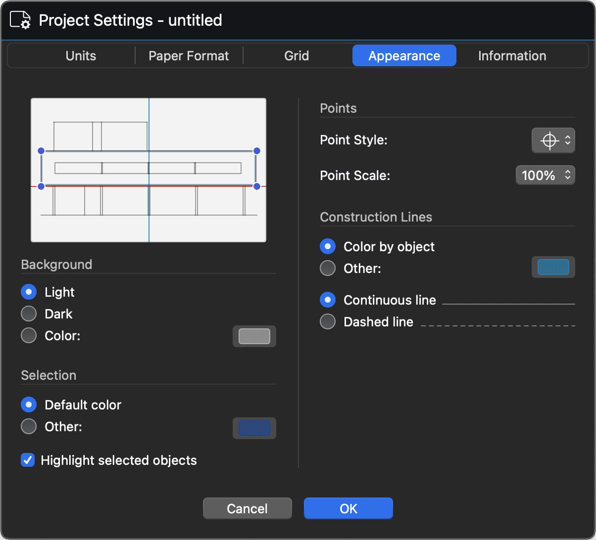
The background color can be set as light, dark or custom. This setting only affects drafting and detail sheets. Layouts always use white as background color.
You can define the color of the selection handles and highlights, and choose to turn highlighting off on selected objects.
The next section includes controls for construction points and lines. These settings are global and change the appearance of all construction objects in the project.
Project Units
Use the Units panel to set the project units and specify the formatting rules. To access the Project Units panel, choose the menu item File > Project Settings > Units or Project > Project Settings > Project Units.
 _
_
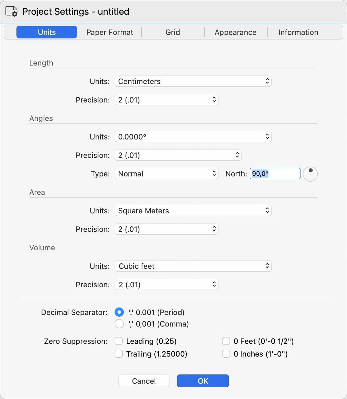
The panel is organized in sections that let you specify the units for lengths, angles, area and volume, and includes options to select the decimal separator and suppress the zero digits.
The settings in this panel act as default settings for all items and tools of the software. Some objects, like Dimensions, also allow custom settings for units in addition to the default, project-wide settings.
Length
Defines the units that show linear measures. Use the Units menu to select the desired measurement unit and the Precision menu to specify the rounding. Changing the precision does not affect that actual value stored in the project, but only changes the way that value is displayed in the software.
- Decimal units can have a precision in the range from 0 (no decimal digits) to 8 decimal digits.
- Fractional units can be set to a precision from 1/2 to 1/64
Angles
Angles can be expressed in a number of standards:
- Decimal degrees (0.0000°)
- Degrees and minutes (0° 0')
- Degrees, minutes and seconds (0° 0’ 0’')
- Radians (0-2 Pi)
- Centesimal (0-400 gradians)
Angle precision ranges from 0 (no decimals) to four decimal digits (0.0001).
Angles can also be expressed as Normal, Bearings and Azimuth relative to the North.
The Angles section also includes a control to specify the project north.
Area
Areas can be displayed in international or imperial square units, or square points. Their precision ranges from 0 to 8 decimal units.
Volume
Similarly to area units, volume units are available in both international and imperial cubic units, with precision ranging from none (0) to four decimal digits.
Display Options
You can set the decimal separator character as comma (",") or dot ("."). While this setting affects displayed units, you can enter units either way as you are more accustomed to and the software will accept and parse your input.
You can also decide to trim leading, or initial, and final, or leading, zeros from numbers. For example, when leading zeroes are suppressed, 0.25 is displayed as .25 and when trailing zeroes are suppressed 1.25000 becomes 1.25.
Fractional units can also be displayed with or without 0 feet and 0 inches.
Paper Formats
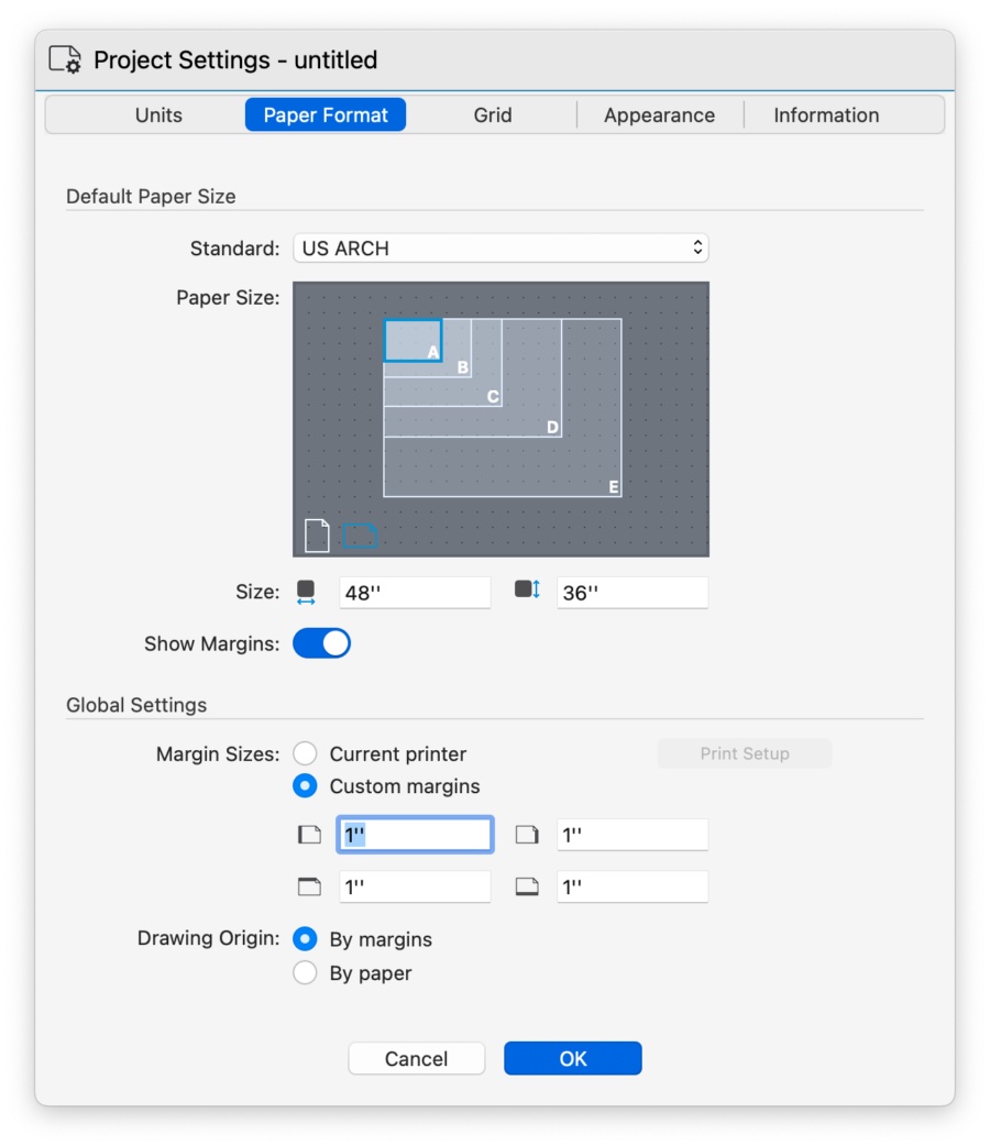
The Paper Formats panel lets you select the default paper size of the entire project from a list of standard sizes (ISO, ANSI/ASME, US ARCH, and more) and activate the options for Page orientation and margins. The page standard and size defined in this window is the default for all new layouts.
Default Paper Size
To set the dafault paper size:
- Choose the reference standard from the list of common paper size standards: ISO, North American, ANSI/ASME, and custom sizes.
- Once you select the standard, the Paper Size view shows the paper sizes from that standard. Click a size to select it and choose the orientation by clicking the Portrait or Landscape icons.
- The Width and Height fields show the dimensions of the selected size. The fields are not editable for default sizes, but can be used to define a custom paper size.
- Use the Show Margins switch to display or hide the margins of the paper.
Global Settings
Use this section to define the margins of the paper. These settings apply to all sheets regardless of the current paper size.
Select Current Printer to inherit the margins from the current printer, or Custom Margins to enter them using the input fields.
Drawing Origin
This setting controls the location of the origin of the drawing in a layout.
- The default setting “By margins” places the origin of the drawing at the lower-leftcorner of the page margins. When this is active, changing the page margins will not affect the relative position of the drawing on the layout.
- The “By paper” setting places the origin of the drawing at the lower-left conrner of the physical paper. With this setting, changing the page margins also affects the relative position of the drawing.
Important
Projects created with HighDesign R8.1 default to “Origin by paper”. If you want to change this setting in older projects, remember that the position of the drawings on the layout may need to be updated.
Custom Paper Sizes
You can define custom paper sizes with the Custom Paper Sizes dialog window.
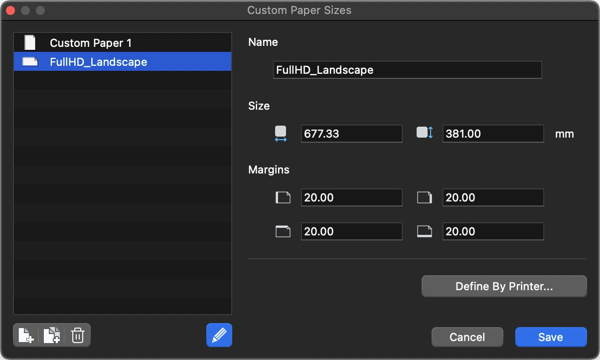
You can access this window from the Standard menu to create and manage custom paper sizes. A custom paper size can have user-defined size and margins, or it can inherit the actual values from an installed printer. Click the “Define by Printer” button to open the system printer dialog to select a printer and a paper size.
Saved presets can be renamed, edited and duplicated and deleted at any time. They are also available in the Paper Size windows of sheets and layouts.
Project Grid
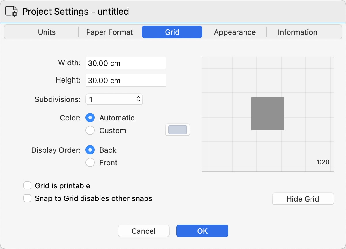
You can use this pane to customize the project grid and set its options. The project grid is a graphical aid that displays a grid with major and minor divisions on all drawing sheets. The size of the grid is at 1:1 scale and is displayed at the scale of the current sheet. For example, a 30x30 cm grid will appear larger when switching from a 1:20 sheet to a 1:10 sheet.
 _
_
To define the grid:
- Define its real-world size using the Width and Height fields.
- Define the number of subdivisions from a minimum of 1 to a maximum of 12. A subdivision value of 1 means that no subgrid will be displayed.
- Define its color. The Automatic color is calculated as a dimmed contrast color to the current background defined in the Appearance panel.
- With the Display Order controls you ca choose whether to display the grid behind the drawing or in front of it.
By default, the project grid is hidden on printouts. Activate the Grid is printable checkbox to make the grid visible on printouts.
The project grid can be used with the Snap to Grid option. You can also choose to make this type of snap exclusive so that all other snaps are disabled when Snap to grid is turned on.
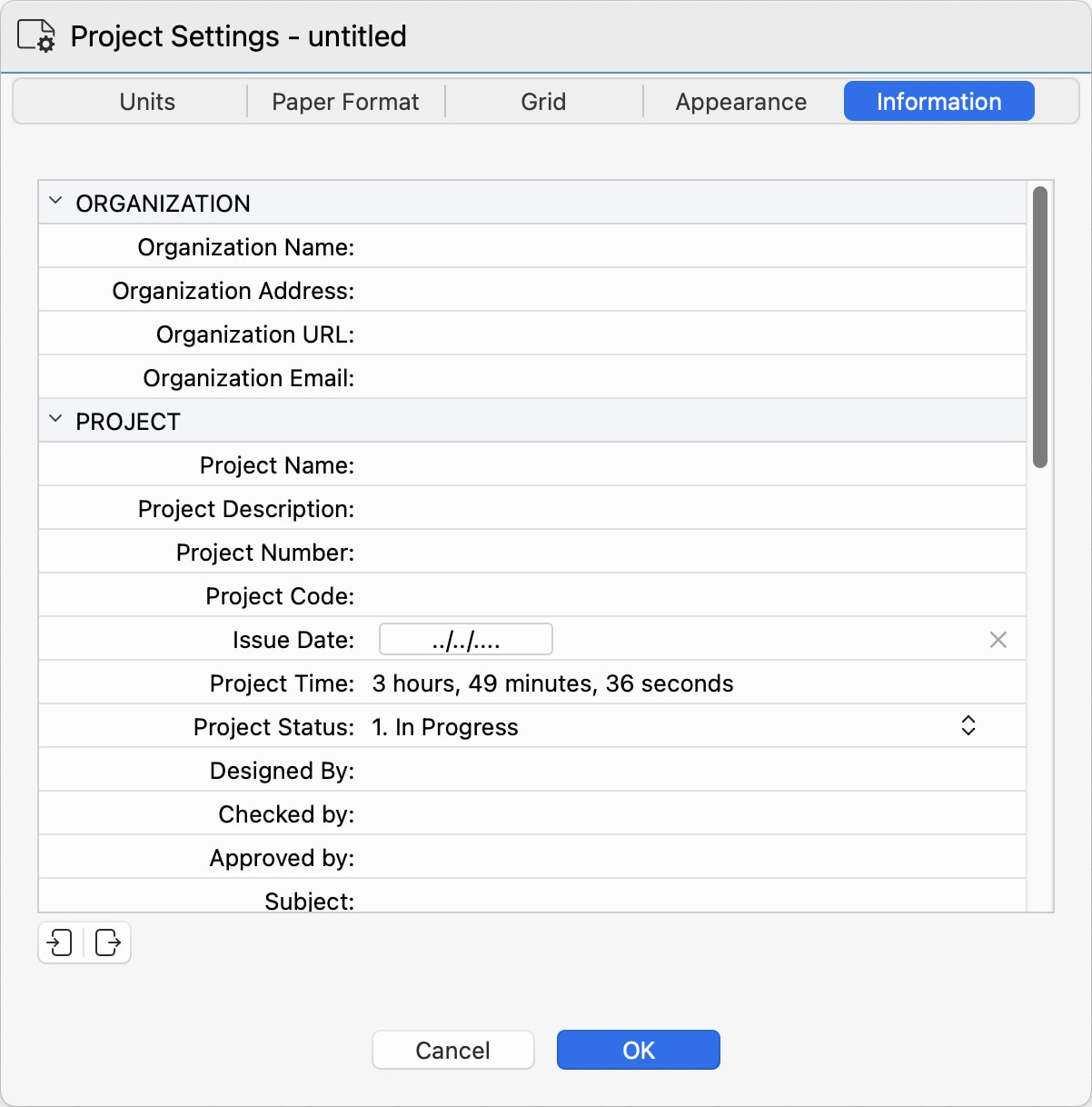
Project Information
Use this panel to enter all the information about the current project, such as your organization name, project name and code, client, site, etc.
The Project Information panel is only available in HighDesign Pro.
 _
_
These information will be used throughout the project by variables, schedules, and title blocks.
The data can be exported and imported as a Comma-Separated-Value (CSV) or XML file.
Essential Skills
Topics in this section
Subsections of Essential Skills
Coordinates, Distances, and Angles
The Input fields are grouped together in the middle of the Input Bar: use these fields to enter the values of constrained coordinates, length and angle of the object you are drawing. The X, Y and L fields also support additions of partial values.
When you click on one field or use the keyboard shortcut, a visual aid shows up to point the current constraint out.
In all input fields, values can be entered either as numbers, such as “100”, or as a sum of numbers, such as “100+20+60”.
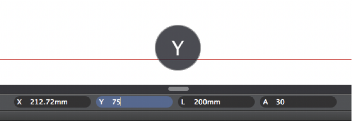
X and Y Coordinates
Coordinates in HighDesign are either absolute or relative. Absolute coordinates are calculated from the global origin point of the drawing, and relative coordinates are calculated from the previous point of the object.
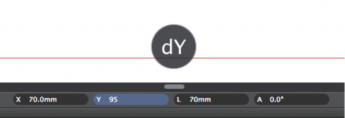
The insertion point of an object, that is its start point, is always set and viewed in absolute coordinates, with the X and Y values calculated from the origin of the current sheet. The next point is relative by default, but you can change it from relative to absolute by clicking the X or Y icon on the input field.
For example, in a line with points at (20, 20) and (100, 100), the end point is (100, 100) in absolute coordinates and (80, 80) in relative coordinates.
To set the absolute insertion point:
- Click on the corresponding input field or press the “X” or “Y” keys on the keyboard;
- Enter the desired X or Y distance from the Origin;
- Press Return to confirm.
**To set the relative end point: **
- Click on the coordinates fields or press the “X” or “Y” keys on the keyboard;
- Enter the desired dx or dy distance from the start point;
- Press Return to confirm.
You can change from relative to absolute coordinates and vice-versa by clicking the X or Y icon on the input field or using the corresponding key shortcuts.
Constrained Length
You can constrain a segment, line or radius to a fixed length after you have set the start point. In HighDesign, there are two methods for constraining a length that can be used interchangeably.
A. Define direction, set length.
- After the insertion point is set, move the pointer at the desired angle of the next point;
- Enter the desired length, either as a total length or as a sum of partial values;
- Press Return to confirm;
B. Define length, set direction.
- Click on the Length field or push the “L” key on the keyboard;
- Enter the desired length;
- Press Return to confirm;
- Move the pointer to set the angle of the vector.

Constrained Angle
To constrain the pointer movement to a fixed angle:
- Click on the “A” field (Angle) or push the “A” key on the keyboard;
- Enter the desired angle value (in degrees);
- Press Return to confirm;
- Move the pointer to set the desired length.
Relative Angle
It is possible to constrain the pointer to a relative angle to a reference direction:
- Click on the “A” field or push the “A” key on the keyboard;
- Enter the desired angle value (do not push the “Enter” key);
- Click on the reference direction (line, poly-line segment or wall);
- Move the pointer to set the destination length.
Constrained Distance
To set the distance of the insertion/start point of an object from a datum point, type the value, push Enter and click on the datum point; the distance is now displayed as a radius from the datum point: click to set the insertion/start point of the object.
 _
_
Activate drawing constraints by using the TAB key
Drawing constraints for X and Y coordinates, Length and Angle can also be activated by pressing the Tab key on the keyboard. When you first push that key it activates the X constraint; then, in order, Y, L, A. Activating the Y constraint stores any values inserted into the X field, so to make it easier to set the coordinates of a point.
Geometric Constraints
The Drawing Constraint functions allow you to quickly draw items with some conditions, such as parallelism, defined angle or intersections. The Input Fields on the Input Bar allow you to enter the coordinates of drawing points and the geometric dimensions of the objects, like length and angle.
Constrained Directions
Linear or polygonal graphic objects such as lines and Poly-lines, rotated rectangles, hatches, arcs and ellipses by radius and diameter, dimensions and walls, can be drawn aligned with one of the Cartesian Axes or rotated by steps of 15 degrees: to do this, just press the Shift key while moving the pointer.
Constrained Parallel, Right-Angle and Aligned/Tangent
These three buttons on the Input Bar provide the Right-Angle and Parallel constraints and the Intersected condition.
Constrain Parallel (P) and Right-Angle (R)
These conditions can be activated anytime with any tool or editing function and will affect the direction of the current movement.
To activate the Right-Angle or Parallel condition:
- After the first click of the current operation you are performing, click the button corresponding to the desired condition or press its keyboard equivalent (P or R);
- Click the reference object, e.g. the line you want to draw perpendicular or parallel to (the mouse-cursor changes to a pointing hand when on a valid object);
- To cancel a condition, press the Esc key on the keyboard.
Constrain Aligned/Tangent
This condition constrains the pointer to intersect a reference line or circle, extending the line you are drawing to the intersection point, even outside the segment bounds, or constraining the direction to the tangent.
To activate this condition, click the button in the Input Bar or press its keyboard equivalent. If the condition is activated before the start point is defined, it constrains the start point to be aligned to the line or tangent to the circle. If activated after the first click, it constrains the end point.
The same result can be achieved by pressing the Command key + click on the datum line while drawing the line, polygon, wall or hatch/fill.
The Constrain Tangent option can be activated to construct a line tangent to an arc or circle, either from the starting point or to the end point.
To construct a line tangent to an arc or circle from the start point:
- Activate the Constrain Tangent option.
- Click on the reference arc or circle. As you move the pointer, the start point of the segment will keep the tangent condition that is closest to the clicked point.
To construct a line tangent to an arc or circle on the end point:
- Click to define the start point of the line.
- Activate the Constrain Tangent option.
- Click on the reference arc or circle.
The drawing constraints and the snap options can also be displayed as grouped in a floating window you can move to a convenient position on the screen. To show this option, select “Snaps” on the Window menu.
Alignments
When the pointer snaps to one endpoint of an object, that location is stored as current origin of the temporary guides; the guides are displayed when the cursor is on the X-axis or Y-axis of that datum point.
The pointer also snaps to the intersection of the guides: the intersection is highlighted with one point and both the guides visible.
 _
_
Furthermore, when you place the pointer over a segment, this function stores the angle of that segment displaying the corresponding parallel and orthogonal guides: when tracing the line, just place the pointer over one datum point of that segment (endpoints or midpoint) to display the alignment.
To temporarily disable the Snap to alignments, hold the “cmd” key (Mac) or “ctrl” (Windows).
Snaps
Snapping is a function that allows the precise positioning of objects and insertion points by having some points of the canvas or parts of objects attract the cursor. It behaves like a magnetic property that adjusts the cursor position when it is within a certain range. HighDesign provides automatic snap to grid nodes, object body, vertex, intersection, right-angle / tangent and alignments.Snaps can be toggled on and off through the Snaps menu on the bottom-left hand side of the main window in the Input Bar. Snap options can also be displayed as a handy floating window available via the Window menu.
Snap Types
The Snap function is always highlighted by a different shape of the pointer and marked by a handle on the screen that correspond to the current snap condition. Depending on the current preferences, the type of snap can also be highlighted by an on-screen label and a sound.
The available snap options correspond to the following snap types:
- Snap to grid: the pointer snaps to grid intersections and its sub-divisions;
- Snap to endpoint or vertex;
- Snap to object: the pointer recognises a minimum distance from an object body;
- Snap to intersection: all intersections are interpreted as endpoints;
- Snap to right-angle: the pointer changes when the current segment intersects another one with a right angle;
- Snap to tangent: the pointer changes when the current line is tangent to a circle / arc;
- Snap to alignments: the pointer snaps to two temporary guides;
- Snap to Sub-Objects: allows to snap to the objects inside the instances of symbols inserted into the project and inside the Viewports inserted in Layouts.
Select Objects
The Arrow tool lets you select drawing objects by clicking directly on them or by defining a selection area. To select an object, click on it with the arrow tool. Snap to Objects must be active so that the arrow tool can “see” the object you are clicking.
Methods
Rectangular selection
Click on a blank part of the screen and move the pointer to define a rectangle: objects with control points within the rectangle will be selected. If you move top-to-down, the selection will include all partially or fully enclosed objects (inclusive selection); if you move down-to-top, the selection will include only fully enclosed objects (exclusive selection). You can invert the selection mode at any time by holding down the Alt (Option) key.
Inclusive and exclusive selection modes_
Polygonal selection
Use this method to select objects by defining a polygonal region. Click to add a vertex to the selection region, double-click to end
Adding and removing objects
Hold down the Shift key while clicking to add items to the selection or remove already selected items. Click on a blank part of the screen to deselect all. If the option “Arrow tool clicks extend selection” is active in Preferences, clicking an unselected object will automatically add it to the selection.
Selecting overlapping objects
When two or more items overlap it can be difficult to select the right object. To get a smart selection, activate the Arrow tool, hold the Control key and click or right-click on the intersection to open a contextual menu with a list of all the objects at that location, from top to bottom.
_
Editing objects
The Arrow tool can also be used as an all-purpose editing tool: most of the tool-specific editing actions, such as resizing a line or editing a text, can also be performed with the Arrow tool.
- Clicking a selected object on its outline, but not on a vertex, will activate the Move function.
- Clicking a vertex of an object resizes the object.
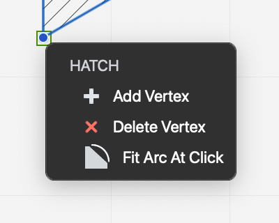
- Hovering the cursor on a vertex of a selected hatch, polyline or spline opens the menu with the options to edit the vertex.
- Hold down the Command key to move any object, selected or unselected, by any of its vertices or by its outline.
Zoom and Pan
These viewing tools, by default grouped in a handy dock on the border of the drawing area, are essential to handle drawings. The first time you launch HighDesign Panning, Zoom and Zoom to fit are docked as semi-transparent buttons on the top right corner of the drawing area: by right-clicking on the dock you can open a menu with the options to change the position of the dock.
Also, in the Zoom and Scrolling section of the Workspace pane of HighDesign Preferences you can open the “View controls” menu to change the position of the dock or to display the controls in the main toolbar.
Zoom
The Zoom tool allows you to enlarge or reduce the current view of the drawing by zooming in or out.
Click on the start point, then move the pointer and click again the define the rectangular area that will be zoomed. Hold down the Option key to zoom out.
The zoom factor is inversely proportional to the size of the zoom rectangle, that is, the smaller the rectangle is, the higher will be the factor.
Double-click the tool icon to set the view factor back to 100% (actual view).
Other zoom commands are grouped under the View menu, including “Zoom to Fit”, “Zoom In” and “Zoom Out”.
Dynamic zoom is enabled by pressing “cmd and +” or “cmd and -” buttons on the keyboard or, with a multi-button mouse, by rotating the wheel: rotate the wheel forward to zoom in and backward to zoom out. Trackpad gestures are also supported by the dynamic zoom.
Zoom to Fit
This viewing utility control is also available as a button in the dock of the viewing tools: by clicking this button the zoom factor and the center of the view are adjusted to fit the extents of the drawing area. This way you get a panoramic view of the whole visible drawing.
When one or more objects are selected this control centers the view of the selection only.
Pan
Use this tool to drag the drawing area and quickly move the current view. To use the Panning Tool click and drag the mouse pointer.Double-click the tool icon to set the view to the center of the drawing.
The panning tool can also be temporarily activated with any tool by pressing the space bar on the keyboard: if you already started a task, for instance drawing a line, the use of the panning tool will not interfere with the current function.
With a multi-button mouse it is possible to pan the drawing by clicking the middle / wheel button and dragging the pointer.