Subsections of Editing Objects
Select Objects
Subsections of Select Objects
Searching Objects
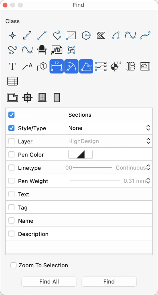
To search items within a project select **Edit ▸ Find… **to open the “Find” window.The Find dialog lets you search items within the current sheet setting criteria to reduce the scope of the function.
The upper section of the Search window shows the buttons corresponding to the graphic objects you want to find within the currently selected sheet. These objects are arranged in three groups: Drafting objects, Documentation objects and Architectural elements.
The optional search criteria offer the menus and fields needed to filter the search.
 _
_
Search Criteria
- Object Class: push the button corresponding to the object class you want to find;
- Sheet: select the sheet, drafting sheet, detail or layout (SE& Pro);
- Style/Type: search items with a style or type (Pro);
- Layer: search items within the selected layer;
- Pen Color: stroke color of the objects to find;
- Line-type: line type of the items to find;
- Pen Weight: pen weight of the items to find;
- Text: search for all occurrences of the text in the drawing;
- Tag: enter the known tag to search elements with that tag (Pro);
- Name: enter the name of architectural elements (Pro);
- Description: enter the description to search matching architectural items (Pro).
The option “Zoom to selection” focuses the view on the objects that match the criteria.
The command Find All selects all the objects that match the criteria.
The command Find selects the objects one by one.
Selection Commands
The Edit menu includes commands to quickly select items with some conditions. Apart from the “Select All Sheets” command, all selection functions apply to the current sheet. The selection commands follow the state of layers, and items on hidden or locked layers are not selected.
- Select All Sheets selects all elements on all drafting sheets (SE & Pro);
- Select All command selects all the elements on the current sheet;
- Select Current Layer to select all the objects with the current layer;
- Select All <object class>… selects all the elements on the current sheet of the sameclass as the currently selected drawing tool;
- Invert Selection selects all the elements and deselects those that were already selected;
- Deselect deselects all the currently selected items.
- Restore Last Selection: restores the last used selection even after having beendeactivated.
Selection Tool
The Selection (Arrow) tool lets you select drawing objects by clicking directly on them or by defining a selection area. To select an object, click on it with the arrow tool. Snap to Objects must be active so that the arrow tool can “see” the object you are clicking.
Rectangular selection
Click on a blank part of the screen and move the pointer to define a rectangle: objects with control points within the rectangle will be selected. If you move top-to-down, the selection will include all partially or fully enclosed objects (inclusive selection); if you move down-to-top, the selection will include only fully enclosed objects (exclusive selection). You can invert the selection mode at any time by holding down the Alt (Option) key.
Inclusive and exclusive selection modes_
Polygonal selection
Use this method to select objects by defining a polygonal region. Click to add a vertex to the selection region, double-click to end
Adding and removing objects
Hold down the Shift key while clicking to add items to the selection or remove already selected items. Click on a blank part of the screen to deselect all. If the option “Arrow tool clicks extend selection” is active in Preferences, clicking an unselected object will automatically add it to the selection.
Selecting overlapping objects
When two or more items overlap it can be difficult to select the right object. To get a smart selection, activate the Arrow tool, hold the Control key and click or right-click on the intersection to open a contextual menu with a list of all the objects at that location, from top to bottom.
 _
_
Editing objects
The Arrow tool can also be used as an all-purpose editing tool: most of the tool-specific editing actions, such as resizing a line or editing a text, can also be performed with the Arrow tool.
- Clicking a selected object on its outline, but not on a vertex, will activate the Move function.
- Clicking a vertex of an object resizes the object.
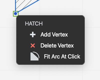
- Hovering the cursor on a vertex of a selected hatch, polyline or spline opens the menu with the options to edit the vertex.
- Hold down the Command key to move any object, selected or unselected, by any of its vertices or by its outline.
Basic Editing
Subsections of Basic Editing
Align Objects
This command moves the selected objects sorting them by their position and the chosen rule. Alignments by a direction use the first object in that direction among the selected objects as alignment margin. For example, Align to Left Margin uses the left-most point of all selected objects as left alignment margin.
The alignment rules are:
- Left margin;
- Center in column: aligns the objects vertically;
- Top margin;
- Center in row: aligns the objects horizontally;
- Bottom margin.
Arrange Objects
Objects can be arranged on the drawing area both by their Z-axis, to control their stacking order, distributed on the plane so that they are spaced evenly and aligned by their selection bounds.
Objects can be arranged on the drawing area both by their Z-axis, to control their stacking order, distributed on the plane so that they are spaced evenly and aligned by their selection bounds.
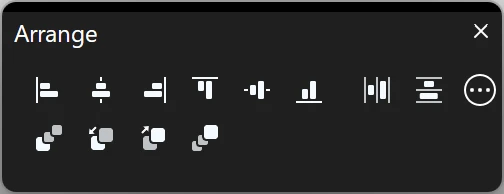
The Arrange Panel
The Arrange panel displays the buttons for all the Arrange Order, Align and Distribute objects commands. Those commands modify the position of the selected objects according to specific rules shown as menu options.
 _
_
Copy as Image
The Copy As Image menu items let you copy the selected objects as image into the system clipboard, for use in other graphics software. The objects are copied as images in one of the following formats and resolutions:
- PNG at 72 DPI
- PNG at 300 DPI
- PNG at 300 DPI with alpha channel
- JPEG at 72 DPI
- GIF
The objects are copied at the current zoom factor, and the higher the resolution, the more memory is required to create the image. Since projects in HighDesign are made of vector elements that can be zoomed in almost indefinitely, it is possible to run into low-memory situations when copying a large project as image. Reduce the zoom or copy one area at the time to work around possible hardware limitations.
Cut, Copy, Paste and Delete
These are standard functions you find in all programs and provide some simple yet useful actions:
- Cut means that selected items will be deleted from the drawing and put in memory for later use;
- Copy means copying the selected items to memory, without removing them from the project;
- Paste lets you insert items stored in memory;
- Delete is used to erase selected items from a project.
Objects copied from HighDesign are not stored in the system’s clipboard, but rather use an internal copy and paste method, so that the system clipboard is available for images and texts.
The Paste command opens a dialog with options that allow to choose the source from which to paste the objects, whether the system clipboard or the HighDesign clipboard. Other options include the location of the pasted object and the destination layer.
Distribute Objects
Every object has a bounding box that defines the maximum extents of its dimensions. The Distribute command allows you to position the selected objects according to the space between the bounding rectangles. The first and last objects in the selected direction define the margins.
The options are:
- Left Margin
- Center in Row
- Right Margin
- Horizontal Spacing:
- Top Margin
- Center in Column
- Bottom Margin
- Vertical Spacing
Undo and Redo
Most operations in HighDesign can be undone (and redone) up to 300 steps back, thus giving you the maximum freedom in experimenting.
“Undo” and “Redo” apply to the following actions:
- Creation of new items (e.g. new Line, new bézier, etc.)
- Deletion of one or more selected items
- Modification of selected items (e.g. extend, modify, trim, drag, etc.)
- Complex operations (e.g. fillet, chamfer, paste, etc.)
In particular situations, it may be useful to suspend the action logging system used by the Undo/Redo commands. The Suspend Undo allows to temporarily put the Undo engine to pause.
Affine Transformations
Affine transformations are geometric transformations that modify the objects so that their lines and internal parallelisms are preserved. These transformations are functions that alter the position, scale and rotation of the objects in a way that the result object is affine to the original object.
Topics in this section
Subsections of Affine Transformations
Flip Horizontal and Vertical
The Flip command mirrors the selected objects around their central point, vertically over their X axis or horizontally over the Y axis.
Flip can only be applied to graphic objects:
- Lines
- Polylines
- Rectangles
- Regular polygons
- Hatches
- Circular arcs
- Ellipses
- Splines
- Bezier paths
- Symbols
- Images
- Groups
Flip an Object
- Select the object
- From the Drawing menu, choose Flip Horizontal or Flip Vertical
Linear Multiply/Distribute
This function creates a number of copies of the selected items. The method can be Increment, where the distance between start and end point define the distance between each copy, or Distribute, where the distance defines the maximum width of the copies. With this option, the distance between the copies is calculated on the number of copies.
 _
_
Applies to
- selected objects
Steps
- Set number of copies and method, Increment or Distribute;
- define the start point, origin of the translation;
- define the end point.
Available Constraints
The Multiply/Distribute dialog can be used entirely with the keyboard: the Up and Down arrow keys control the number of copies; Command + Up/Down arrow controls the option buttons.
- Length (L + value; value);
- Angle (A + value)
Mirror Objects
This command includes the Mirror and Mirror a Copy commands. Mirroring transforms objects by flipping the selection around an arbitrary axis.
The Mirror command modifies the selected object. The Mirror a Copy command creates a reflected copy of the original object.
 _
_
Applies to:
- selected objects
Steps:
- define the start point, origin of the axis;
- define the end point, angle of the axis.
Constraints:
- Angle (A + value)
Move and Duplicate Objects
Move
Use this function to move (translate) selected items. Choose Drawing ▸ Move, then click to set a start point, move the pointer and click again to set direction and offset of the translation.
Applies to
- selected objects
Steps
- define the start point, origin of the translation;
- define the end point.
Available Constraints
- Length (L + value; value)
- Angle (A + value)
By holding down the Alt key, the Move tool turns to Duplicate. The Move command can be activated in other ways too:
- With the Selection tool, or during the editing of an object, by clicking the center point if available;
- With the Arrow keys, or Shift + Arrow key if set in Preferences ▸ Workspace, to move the selected objects by one linear unit; holding down the Alt key the offset is multiplied by 10.
- Holding down the Cmd key, you can click on an object and begin a Move command with one operation.
Duplicate
This function creates a copy of the selected items with a defined offset. Its operation is very similar to the Move command.
The Duplicate function can also be activated by the Arrow tool by pressing the Option key while moving selected items.
Hold down the Command key to make multiple copies of the same selection in one session.
Applies to
- selected objects
Steps
- define the start point, origin of the translation;
- define the end point.
Available Constraints
- Length (L + value; value)
- Angle (A + value)
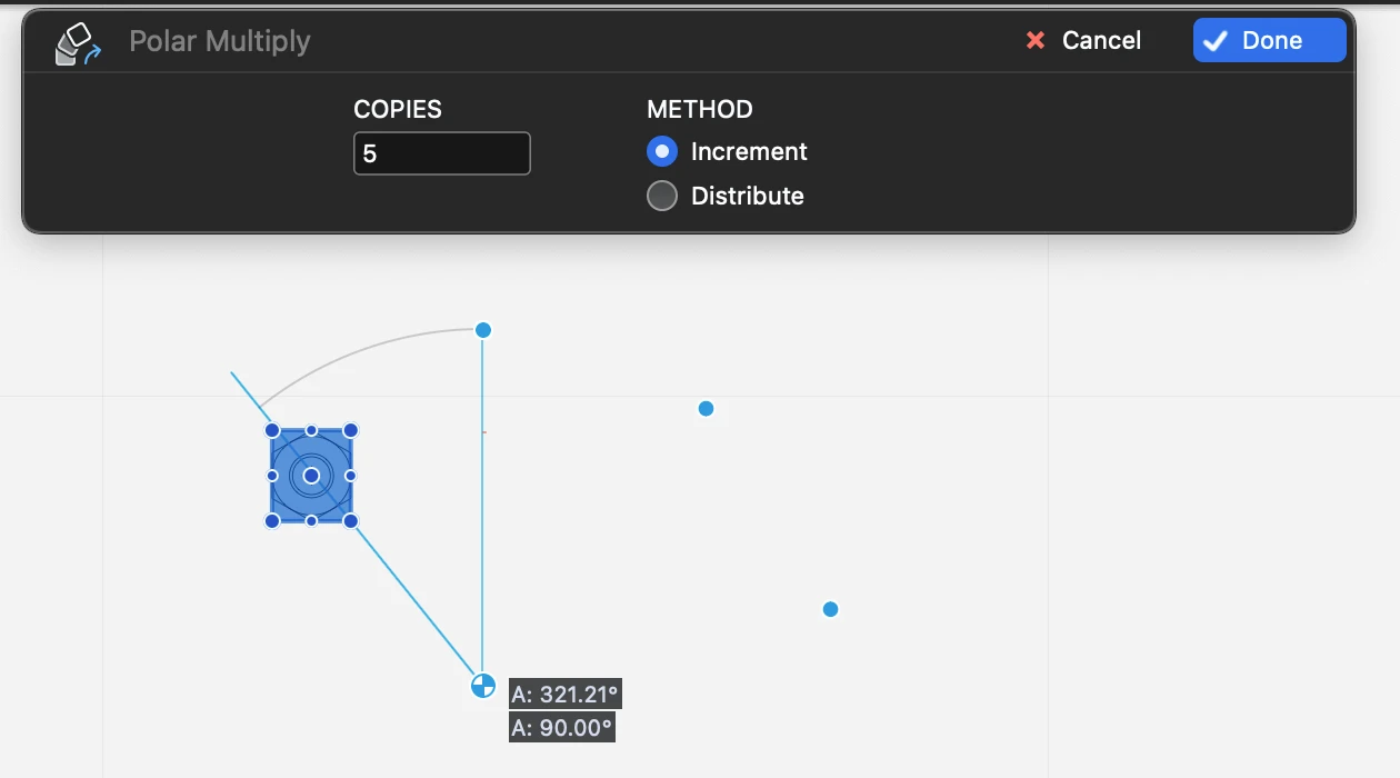
Polar Multiply/Distribute
Use this tool to create multiple copies of selected objects along a circular arc. The menu item Drawing ▸ Polar Multiply opens the input dialog used to enter the number of copies and select between increment and distribute.
 _
_
Applies to:
- selected objects
Steps
- Set number of copies and method, Increment or Distribute;
- define the center of the rotation;
- define the start point of the arc
- define the end point of the arc.
Available Constraints
- Angle (A + value)
The Polar Multiply/Distribute dialog can be used via the keyboard: the Up and Down arrow keys control the number of copies; Command + Up/Down arrow controls the option buttons.
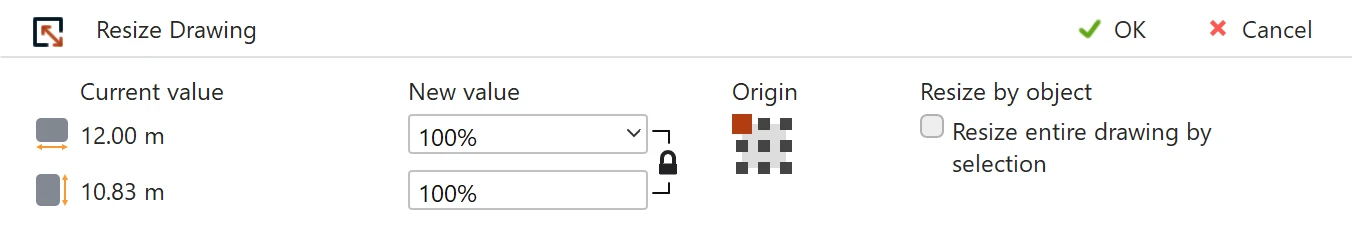
Resize Objects
Use the Resize Drawing tool to change the size of the drawing by a per cent value or by numeric values of width and height. The dimension can be made independent or proportional by clicking the lock icon. The values can be entered in percentage or in any of the supported linear units.
 _
_
Applies to:
- current drawing
- selected objects
Steps:
Constraints:
Constraints:
- scaling can be proportional on both axes. Click the lock proportions icon to control this option.
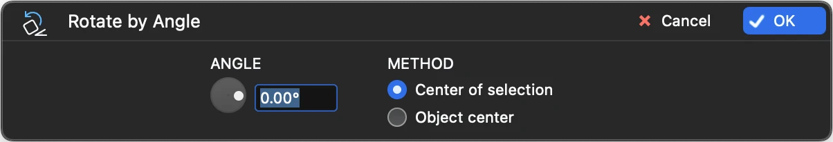
Rotate by Angle
Use this tool to rotate the selected objects in real time. The center of the rotation can be absolute, which is the midpoint of the bounding box of the selection, or the center of the object, which rotates each object around its own center.
 _
_
Applies to:
- selected objects
Steps:
- In the Rotate By Angle window, set the angle by using the slider or entering the value into the input field;
- Choose between global center of the selection and individual object center.
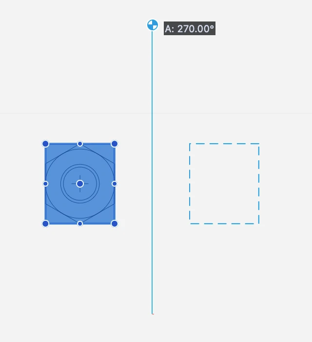
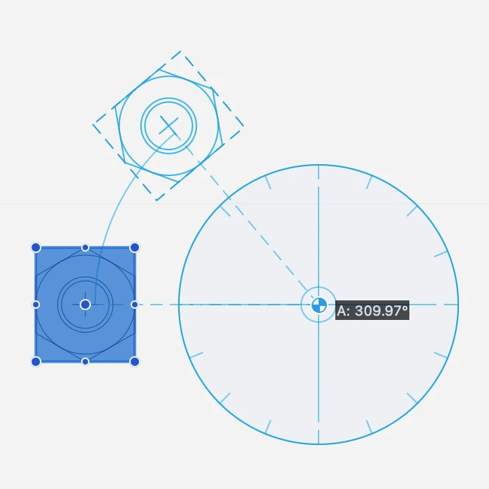
Rotate Objects
This function lets you rotate selected items around a central point and by an angle you define graphically.
 _
_
Applies to:
- selected objects
Steps:
- define the first point, center point of the rotation;
- define the start point;
- define the end point and angle.
Available Constraints:
- Angle (A + value)
You can also enter a rotation angle value by pressing the “A” key on the keyboard between steps 2 and 3.
Stretch Objects
Use this command to pull and resize the objects within the selection rectangle: items which are entirely within the selection rectangle will be moved whereas all other objects will be resized. Arcs, circles, ellipses, text blocks, doors/windows and symbols will be rigidly dragged with no deformation.
 _
_
Applies to:
- selected objects
Steps:
- Define the rectangular area that encloses the points to move. The points are highlighted.
- Specify the start point, that is the origin of the translation.
- Move the pointer in the desired direction.
- Click or use the keyboard shortcuts to specify the end point.
Constraints:
- Length (L + value; value)
- Angle (A + value)
Linear Modifications
Subsections of Linear Modifications
About Linear and Boolean Modifications
This set of commands mostly applies to linear objects with the exception of boolean operations that apply to polygonal shapes.
Topics in this section
- Mark Intersections
- Join
- Extend
- Split
- Trim
- Divide into Parts
- Break
- Boolean Operations
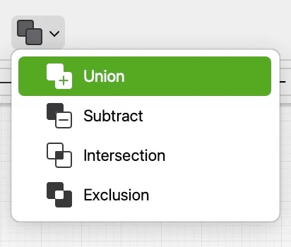
Boolean Operations
Boolean operations combine two polygons using one of the following intersection formulas:
- Union: combines the two polygons together to form a new polygon. The internal intersections are ignored and only the maximum external profile is used to define the new shape.
- Subtract: uses the second polygon as a “clipping” shape to remove the intersecting area from the first polygon.
- Intersection: creates a new shape by the intersection of the two polygons and discards the outer perimeter.
- Exclusion: the opposite of Intersection, it shows only the areas of the two polygons that do not overlap.
 _
_
▶︎ Boolean operations must be applied to linear polygons: rectangles, regular polygons, hatches, polylines with straight segments.
▶︎ The order of selection matters: the first object selected acts as the base shape and the second object as the clipping shape. The polygon resulted from the boolean operation inherits the properties of the base object.
Break
Use this tool to define a segment that will be subtracted from a selected object. The command applies to lines, polylines, arcs and circles, and walls.
Select Drawing ▸ Break, click on a line to set the first point of the segment and click again to set the endpoint.
Applies to:
- Selected object
Steps
- Select the object and activate the command.
- Click on the object to define the first break point.
- Click to define the second break point.
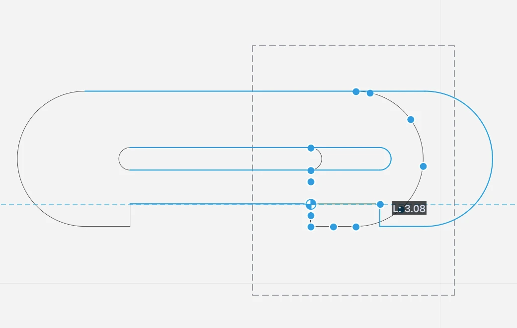
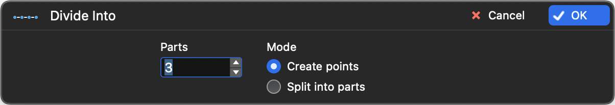
Divide into Parts
This command is used to divide the selected line into the number of equal segments you specify in the Divide Into dialog. This dialog lets you also choose whether divide the line with alignment points or actually create segments.
The command applies to lines, polylines, rectangles, polygons, arcs and circles.
 _
_
Applies to:
- Selected objects
Steps
- Select the object
- Activate the command
- Enter the desired number of parts and select the division mode. Push OK.
The Divide Into dialog can be used via the keyboard: the Up and Down arrow keys control the number of divisions; Command + Up/Down arrow controls the option buttons.
Extend
This function extends the selected lines (either by lengthening or shortening) to their intersection point with another object. Supported types are:
Construction line, Line, Polygon, Rectangle, Spline, Bézier curve, Arc / circle, Wall.
Applies to:
- Selected lines or walls
Steps
- Select an object
- Activate the command
- Click on the destination object
Join
This command connects two linear objects so that they either intersect on one point or form a new object. Lines and walls, being individual objects, intersect; polylines, paths and splines are joined together to form a new object.
The Join command applies to:
- Two lines
- Two walls
- A line and a polyline
- Two polylines
- Two bezier paths
- Two splines
This command does not apply to two different classes of curves, or a spline and a polyline, or two parallel objects.
Applies to:
- **Applies to: **selected objects
- Steps: direct command
Steps:
or
or
- Select an object
- Apply the command
- Click on the destination object
This second method allows you to join objects in sequence.
Mark Intersections
This function finds all possible intersection points between two selected items. The points are marked by simple alignment points created on the current layer and with the default pen color.
This command applies to lines, polylines, rectangles, regular polygons, hatches, curves, and walls.
Applies to:
- selected objects
Steps:
- Select two objects. The objects do not need to intersect each other.
- Apply the command.
Split
This function splits linear objects into segments using another object as “cutter”. The Split command applies to lines, poly-lines, rectangles, arcs, circles, freehands and bezier curves.
Rectangles and polygons are transformed into polylines after the split.
Applies to:
- Selected oobjects
Steps
- Select the object to split
- Activate the command
- Click on the “cutter” object
Trim
The Trim function is a multipurpose function designed to delete linear or curved segments or parts. It applies to single segments without intersections with other objects as well as to segments intersected by other objects.
 _
_
Segments without intersections
Activate the tool and click on the segment to delete: if the trimmed segment belonged to a rectangle or polygon, the remaining segments are turned into poly-lines.
Segments intersecting other objects
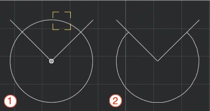
Activate Trim and click on the segment or part of segment to delete: use this tool to clear a drawing and cut segments, arcs and curves between intersections or extending off an edge with just a click.
To apply it:
- Choose Drawing ▸ Trim or click on the corresponding icon of the Edit Tool Bar;
- A visual aid highlights the segments under the pointer (1);
- Click the parts of the objects you want to trim;
- All segments and portions of arcs between intersections or extending off the edge will be deleted (2);
- Click an empty region to quit this command or press the Esc key.
You can also activate the Trim command by holding down the Backspace or Canc keys on the keyboard and clicking the object, or by clicking with the eraser tip of a graphic pen. No selection is required to use this function.
When activated with a selection, the selected objects acts as “cutters” and control the intersections. All intersections that do not belong to a selected object are ignored.
Applies to:
- objects at click
Steps
- click on the destination objects
Advanced Editing Tools
Subsections of Advanced Editing Tools
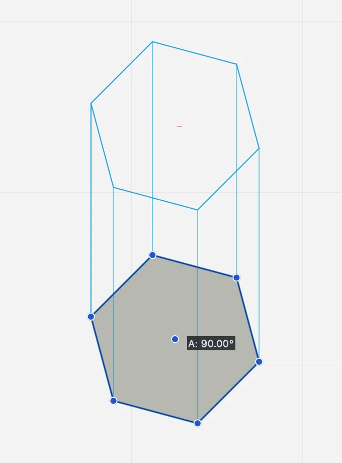
2D Extrude
This graphic function simulates the extrusion along a direction of selected objects by creating projection lines from the vertices to a duplicate of the base object.
 _
_
Applies to
- line
- rectangle
- polygon
- polyline
- hatch
- arc, circle, ellipse
- curves
Steps
About Advanced Editing Tools
This set of tools include commands that perform more advanced modifications to objects, like removing and adding objects, or altering the original object in a significant way.
Topics in this Section
- Fillet and Chamfer Objects
- Offset
- Convert into Polyline
- 2D Extrude
- Explode
- Apply Hatch
- Calculate Area
- Find Center of Mass
- Fit Text Box
- Simplify Curve
Apply Hatch
This command applies a hatch or fill to the region described by the selected items. Supported boundary items are:
- Lines connected by their vertices (“segmented lines”);
- Poly-lines;
- Polygons;
- Freehand lines;
- Bézier curves;
- Splines;
- Arcs;
- Circles;
- Ellipses
To use this tool, select the boundary items, then choose Tools ▸ Apply Hatch: a new fill/ hatch is created with the current settings of the “Hatches and Fills” tool.
Calculate Area
This function calculates the area of a region enclosed by the selected items. Supported boundaries are:
- Lines connected by their vertices (“segmented lines”);
- Poly-lines;
- Polygons;
- Freehand lines;
- Bézier curves;
- Splines;
- Circles, arcs, ellipses.
To use this command, select the boundary items, then choose Tools ▸ Calculate Area: a new text label displaying the area of the region in the current units is created in the center of the selection.
Convert into Polyline
This command converts the selected linear or polygonal objects into a polyline.
Applies to:
- Lines in sequence
- Rectangle
- Polygon
Steps
- Select the objects to convert
- Activate the command
Explode
The Explode command breaks a composite object into its smaller, component objects.
Most of the drawing objects, such as polygons, poly-lines, freehand lines, Bézier curves, arcs and circles, ellipses, hatched polygons, symbols, walls, windows and columns, can be converted to simpler items by the Explode command.
Applies to:
- Selected objects
Steps
- Select the object.
- Activate the command.
The original object is replaced by its component objects. The objects that are created as a result of the explode command retain the layer and the graphical attributes of the original object.
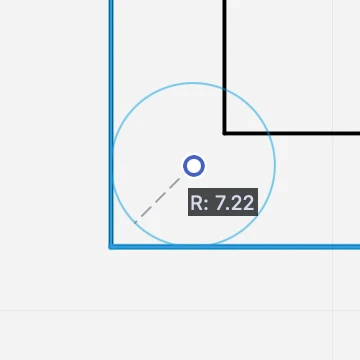
Fillet and Chamfer Objects
These commands connect two segments (lines, poly-lines or sides of a rectangle and regular polygon) with a tangent arc of a given radius, or with an angled line.
Fillet (down) and Chamfer (up) applied to line segments._
These tools can be used via numeric input or graphically
Numeric
- Select two non parallel segments;
- Choose Tools ▸ Fillet or Tools ▸ Chamfer or click on the corresponding icon of the tool bar;
- A text field shows up near the tool icon: insert the value of the radius or the length of the chord and push Enter.
Graphical
The Fillet/Chamfer command can be applied with two graphical methods:
- If you are using method (a), select the two items and activate the Fillet/Chamfer command. If you use method (b), activate the command and click on two items.
- A circle appears between the two items. Click on the handle at the center of the circle and move the pointer to define the radius of the fillet arc or chamfer segment.- 3. While you are defining the radius, enter a value on the keyboard to set its length.
- Click again to confirm.
 _
_
Find Center of Mass
The Center of Mass, sometimes called centroid, barycenter or balance point, is a unique point located at the average position of all the parts of the system, weighted according to their masses. For simple rigid objects with uniform density, the center of mass is located at the centroid. The center of mass is useful because it is the point where any uniform force on the object acts without producing angular acceleration.
The center of mass makes it easy to solve mechanics problems where we have to describe the motion of oddly-shaped objects and complicated systems
The function “Find Center of Mass” calculates the position of the center of mass of the selected polygons, closed poly-lines or hatches. To calculate the center of mass of curved regions like circles or béziers, you can explode them and then apply this command to the selected lines.
Applies to:
- selected objects
Steps
- select the object
- activate the command
Fit Text Box
When you change font or style to the paragraph or even when you import texts from other applications, the text box can be larger or smaller than its actual content: this command adjusts the size of the selected text boxes.
The Fit Text Box calculates the minimum bounding rectangle of the selected text at its current size, with its font and styles. The box of a text block does not automatically adjust as you edit the text properties.
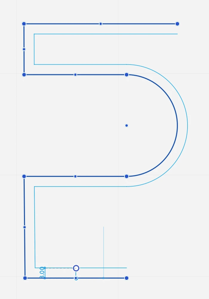
Offset
This tool creates concentric duplicates of linear objects (lines, polygons, rectangles, poly-lines, curves, arcs, circles and ellipses) at a given distance.
To activate the command,
- Select the objects and go to Tools ▸ Offset:
- Enter the distance in the text field that appears next to the tool icon.
- Click on the handle and move the pointer to choose the side you want to place the duplicate on.
Click on the other objects if you want to apply the command with the current settings to other items. Press ESC to exit the command.
 _
_
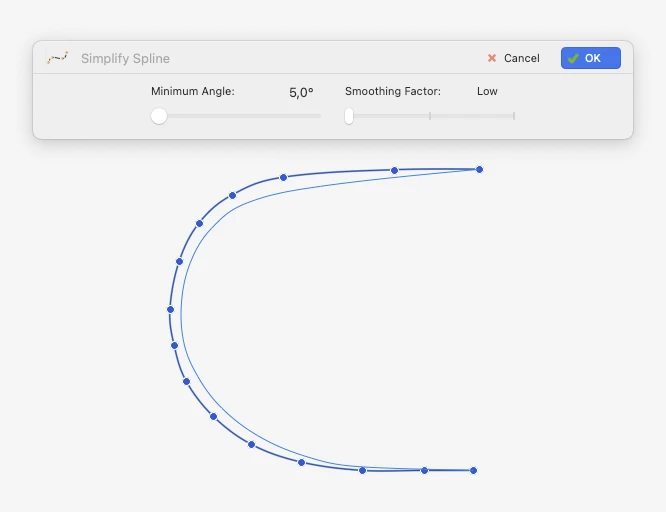
Simplify Curve
Use this tool to reduce the complexity of the selected spline curves by adjusting the angle of the segments defined by the vertices and by selecting a smoothing factor which ranges from Low, through Medium, to High. A real time preview will show the resulting curve. Access this function via Tools ▸ Simplify Spline…
 _
_