Subsections of Architectural Design
Zones
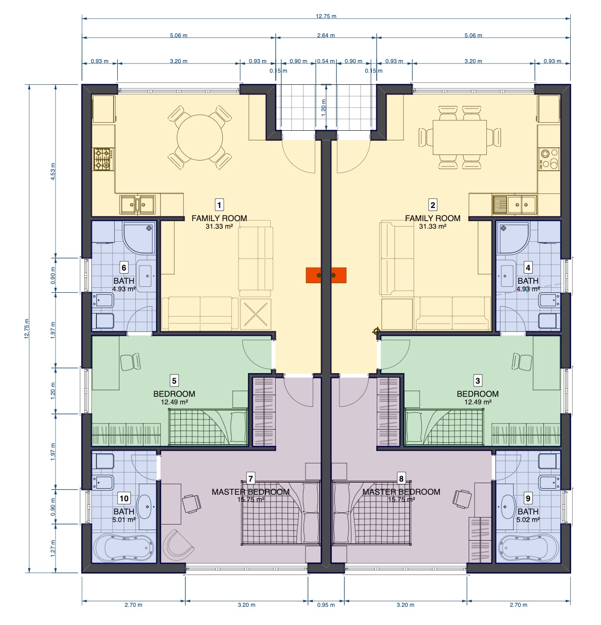
Zones are subdivisions of space identified by their function. Zones typically represent rooms in a floor, wings of a building, or areas in landscape design and city planning. A zone is identified by a unique number, a name and a color.
Info
Zones are computable entities and their properties like layer, name, id, area, etc. are available when you create a schedule that includes the zones of a project.
Topics in this section
Subsections of Zones
Zone Tool Settings
To access the Zone tool settings, choose Edit ▸ Settings Window ▸ Zones or double click the tool icon on the Toolbox.
The Zone settings windows includes two panels: Zone Settings and Names and Colors.
Zone Settings
The Zone Settings panel is organized into two sections, Zone Id and Label.
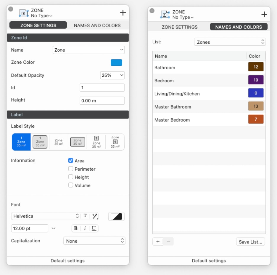
Zone Id
- The Name menu to choose a name from a pre-defined list: the selected names are added in the top most section of the list as Active List of the current project.
- The Zone Color menu opens the Palettes window to select a color. The Zones palette below the Standard HighDesign palette offers 16 pre-defined colors: if there is no choice, the colors are automatically assigned from the Zones palette starting from the first one of the Zones palette.
- The Default Opacity option is set as 25%: the Opacity control allows to set a different value.
- The Id is automatically set in a growing numbered order starting from the firstly created zone.
- The Height option allows to set an average height of the zone in order to get a computed volume in schedules.
Zone Label
The Label section of the Zone Settings panel provides all the options that define the style of the label, or stamp, of the zone and the information displayed in it:
- Label Style, with six different border and style alternatives.
- Information, to select one or more of the following information to be displayed in the label: Area, Perimeter, Height, Volume.
- Font, which offers all the font, color, size, style and capitalization options of the text label of the zones.
Names and Colors
The Names and Colors panel displays the current zone Active List of the project with the names and associated colors. Lick name or color button to make changes.
The List menu provides the default zone lists available in the HighDesign Library, the saved lists available in the User Library or the current list in the Project.
The Save List button allows to save the current list in the User Library to be available in new projects.
Use the “+” and “-“ buttons to add new zones to the list or to delete the selected zone.
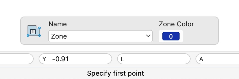
The floating window in the bottom of the drawing window allows the quick selection of the Name and Color properties of a new zone or those changes of the selected zone: it shows up when the Zone tool is active only.
Creating Zones
To create a zone, activate the Zone tool in the Design section of the Toolbox. The Zone tool has three construction methods: Polyline/Automatic, by Rectangle, and by Rotated Rectangle.
Define the combination of name and zone color before the insertion.
You can define the combination of name and fill color of the next zone before its insertion in two ways:
-
Open the Zone settings panel and choose a combination from the active list.
-
Use the options panel that is visible on the screen. By using the name field and pop-up menu you can:
- Enter a new zone name in the text field.
- Open the pop-up menu and select a predefined name and color combination from the active list on the pop-up menu. The current color in the Color button changes to match the selected Zone name-color combination.
- Choose one of the suggested zone names on the pop-up menu.
Zone by Polyline/Automatic Room
With the Zone By Polyline method you can create a zone in two ways:
- Manually by specifying the points of its outline, or
- Automatically by clicking inside a room defined by walls.
To create a room by automatic detection
- Move the pointer over the floor plan. The tool detects rooms enclosed by walls and automatically prepares a zone with default settings.
- Click to confirm the zone. The position of the label is also defined automatically as the center of the polygon and can be modified later once the object is created.
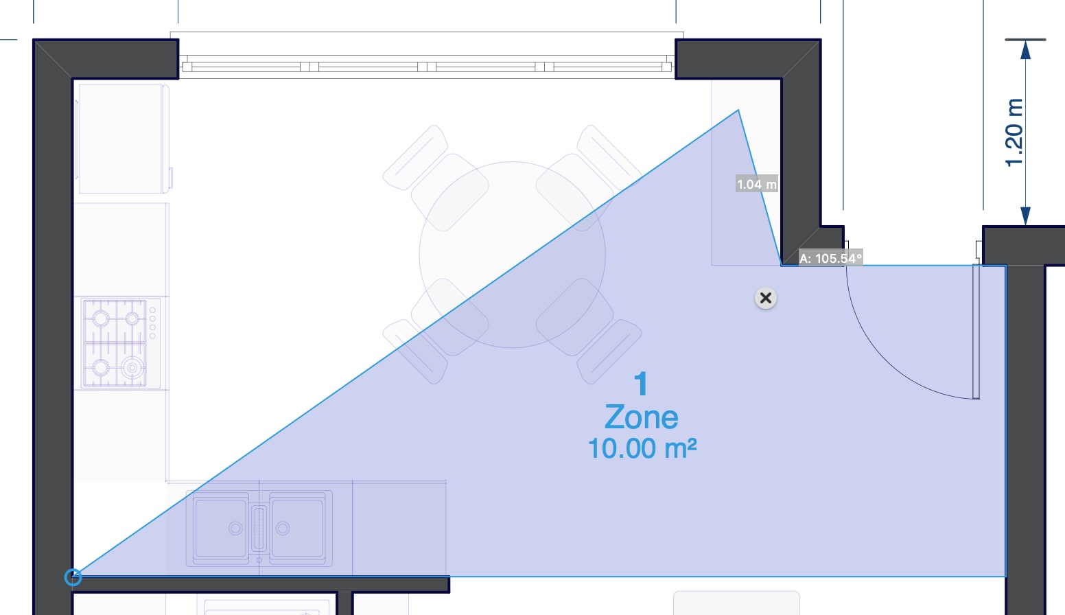
To create a zone by polyline
When no enclosing walls are detected, you can create a zone by defining its shape as a polyline by clicking anywhere on the drawing.
- Click to specify the first point of the polyline.
- Click to specify the next points of the polyline.
- Click on the start point or double click to end the sequence and create the zone.
Tip
Alternatively, even when enclosing walls are detected and a room is automatically generated, you can still define a zone by polyline by holding down Cmd (Mac) or Ctrl (Windows) and clicking to specify the first point.
Zone by rectangle
- Specify the start point of the rectangle.
- Move in any direction and click to specify the opposite point of the rectangle.
Zone by rotated rectangle
- Specify the start point of the rectangle.
- Move in any direction and click to specify the base and rotation of the rectangle.
- Move the pointer and click to specify the height of the rectangle.
Edit Zone Polygon
The boundary of a zone is a 2D polygonal shape that can be edited by moving, adding and deleting vertices, and can be modified with the commands that apply transformations, such as Move, Rotate, Scale, etc.
All editing actions apply to the selected object.
Move a vertex
- Click the vertex and move the pointer to the desired location.
Move a side
- Click the mid-point between two vertices to move the side of the polygon.
Add a vertex
- Hover the pointer on a vertex to open the Zone pop-up menu and select “Add Vertex”. Alternatively, click the desired location of a side of the zone when the “+” sign shows up to add a vertex.
Delete a vertex
- Hover the pointer on a vertex to open the Zone pop-up menu and select “Delete Vertex”. Alternatively, move a vertex to another one till the “-“ sign shows up to delete that vertex.
Other transformations
A zone behaves like a graphic object, therefore other graphic transformations such as Move, Rotate, Mirror, Scale, etc. are applied as in all other graphic entities.
To change name, id, color and label of a zone, select it and use the Object Info or open the Zone Settings window. When the Zone tool is active, a floating window on the bottom of the drawing area allow quick changes of zone name and color of the selection.
Convert to Zone
You can convert poly-lines, polygons, rectangles, hatches/fills to zones through the “Convert to Zone” command on the Tools menu, also available via the Contextual Radial menu.
This command applies to the selected object.
Supported objects
The classes of graphic object that you can convert to zones are:
- Rectangles;
- Polygons;
- Poly-lines, even those with curved sides (concave or convex arcs);
- Hatches and Fills.
The new zone will get the color either from the fill of the selected object (if that object has a fill) or from the default color of the Zone palette. You can change color and label at any time.
Columns
Columns are vertical elements of the building with a structural function. They vary in shape and size, and share some of the properties of walls.
Topics in this section
Subsections of Columns
Column Tool Settings
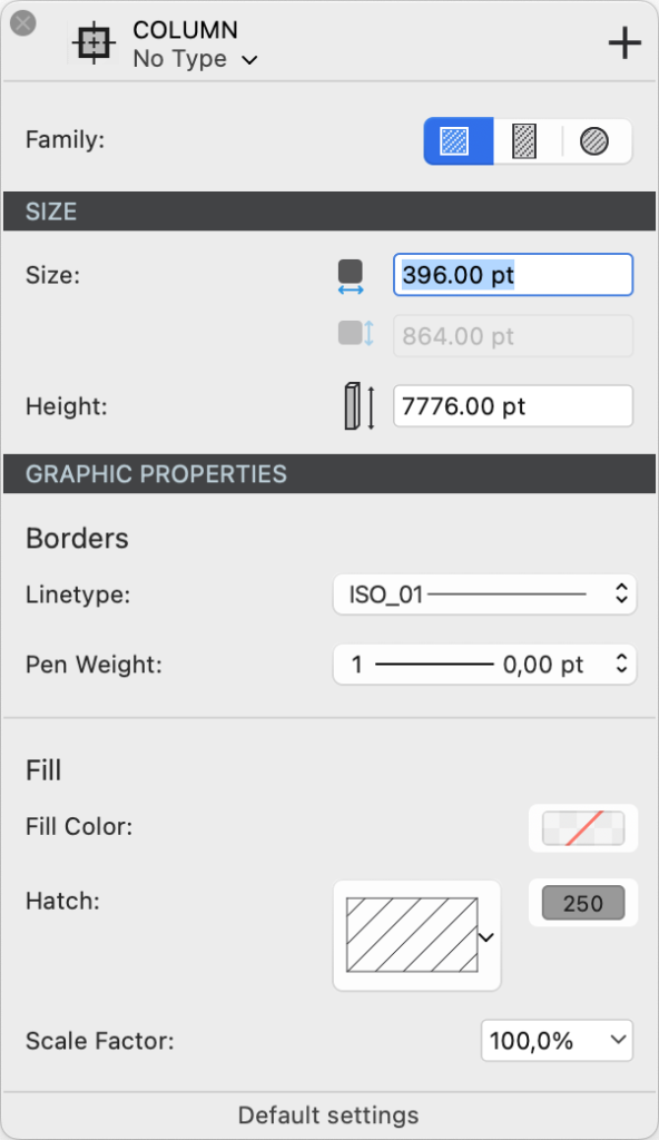
Double click the Column tool icon on the Toolbox to open its Settings panel.
The panel is organized into three sections to define the column’s family, dimensions, and graphic attributes.
 _
_
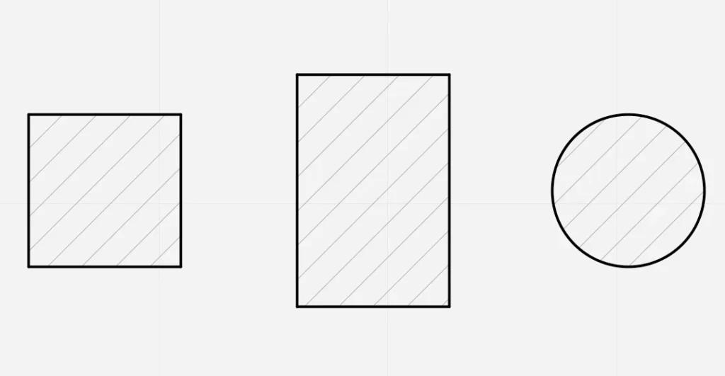
Family
A column’s family is defined by its shape. Click the desired shape choosing from Square, Rectangular and Circular.
Dimensions
You can define base width, base height and height of the column. The base width field is always enabled and in the case of a circular column it defines the diameter of the column.
The base height field is only enabled when the current family is Rectangular column.
The Height field is used for the total height of the column from the base level.
Graphic Attributes
The Graphic Attributes section is divided into two sub-sections: Borders and Fill.
Borders
You can define the line type and the pen weight of the border line of the column in plan view.
Fill
You can add a fill to the column and define:
- A solid fill color
- A vector hatch or pattern and set its color and scale factor.
The fill can use either one of the two fill modes or a combination of the two.
Editing Columns
Move a Column
- Select the column and click its center point.
- Move to the desired location and click to confirm.
Resize
To resize a column, you can use the Column Tool Settings panel, or the Object Info panel.
Editing with the Column Tool Settings panel:
- Select the column and open the Column Tool Settings panel.
- Change the family if you want to reshape the column, or enter the new base width and base height values.
Editing with Object Info:
- Select the column
- Enter the new values for base width, base height and column height.
Place a Column
Before placing a column, choose its type or set is shape, size and graphic attributes in the Column Settings panel.
Columns are always inserted by their central point, so that they align correctly to the structural grid.
- Round columns are inserted with a single click.
- Square and rectangular columns (pillars) require two clicks:
- click to define the center or insertion point;
- move the pointer and click a second time to define the angle of the column. Use the Angle input (A) to enter the desired value.
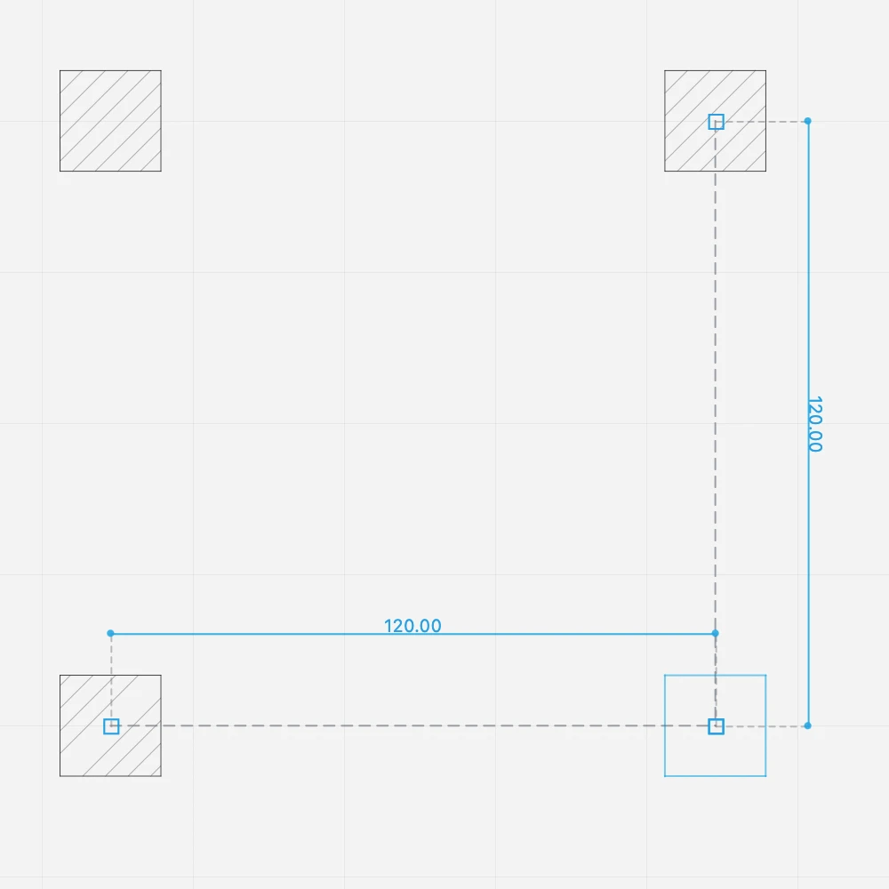
Alignments
When you insert the second column, it automatically aligns with the first column so that you can create the structural grid by placing the columns with just one click.
Square columns also inherit the same orientation as the first column. To change the orientation, hold down the Alt key when you insert the column.
 _
_
To place a column at a fixed distance:
- If not already active, press the Column tool button on the toolbox to activate it.
- As you move the pointer, dimension lines show the distance from the nearest column.
- Enter a distance and press Return or Enter.
The next columns will align to that orientation and snap to the predefined distance.
Walls
The Wall tool allows the creation of walls which are parametric objects, automatically connected on their vertices and borders. To set the attributes, double-click the Wall Tool icon or select Edit ▸ Settings Window ▸ Wall… to open the Wall Settings dialog.
Walls are host elements, in that certain elements like doors and windows can only be inserted in a wall.
Walls are classified into two families: Standard-case Wall, made of one, uniform component, and Composite Wall, made of different internal components.
Topics in this Section
Subsections of Walls
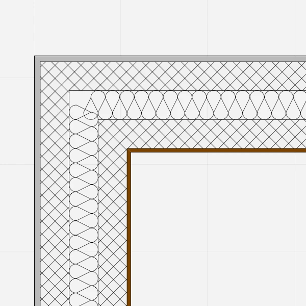
Compound Walls
Compound walls consist of multiple layered components, each with its own properties. Compound walls can only be rectangular in shape, with constant thickness from start to end. The total thickness is calculated as the sum of all the internal components.
_
- Compound walls can have any number of internal components, and you can add, remove, reorder and edit the components at any time through the Components window.
- By default, basic walls and compound walls do not join automatically, because they are different elements that would not be joined in a real situation. Also, they are made of different materials which would not match. However, if a particular situation requires it, you can choose to activate the Allow Joints options and attempt to join two walls of different type.
- Compound walls can use one pen weight for both borders and internal divisions, or you can assign a pen weight for the outer borders, and one for the internal components.
_
Compound Wall Settings Window
- Type pop-up window and New Type icon. This window lists all the available Types, of both basic and compound families. It is advisable to enter descriptive names when saving a new wall type.
- Wall Family.
- Components section:
- Edit Components button to access the Components window; use this button set the components of a new wall or edit an existing wall.
- Total computed thickness; the sum of thickness of the internal components determines the total thickness of the wall.
- Internal pen weight of components. The pen weight can be Same As Borders to set the same pen weight as that used for the borders of the wall, or one of the available pen weights.
- Leading Side: see Basic Wall Properties Window for the description.
- Wall Joints options: see Basic Wall Properties Window for the description.
- Border line type and pen weight. Internal components can only have a continuous line division.
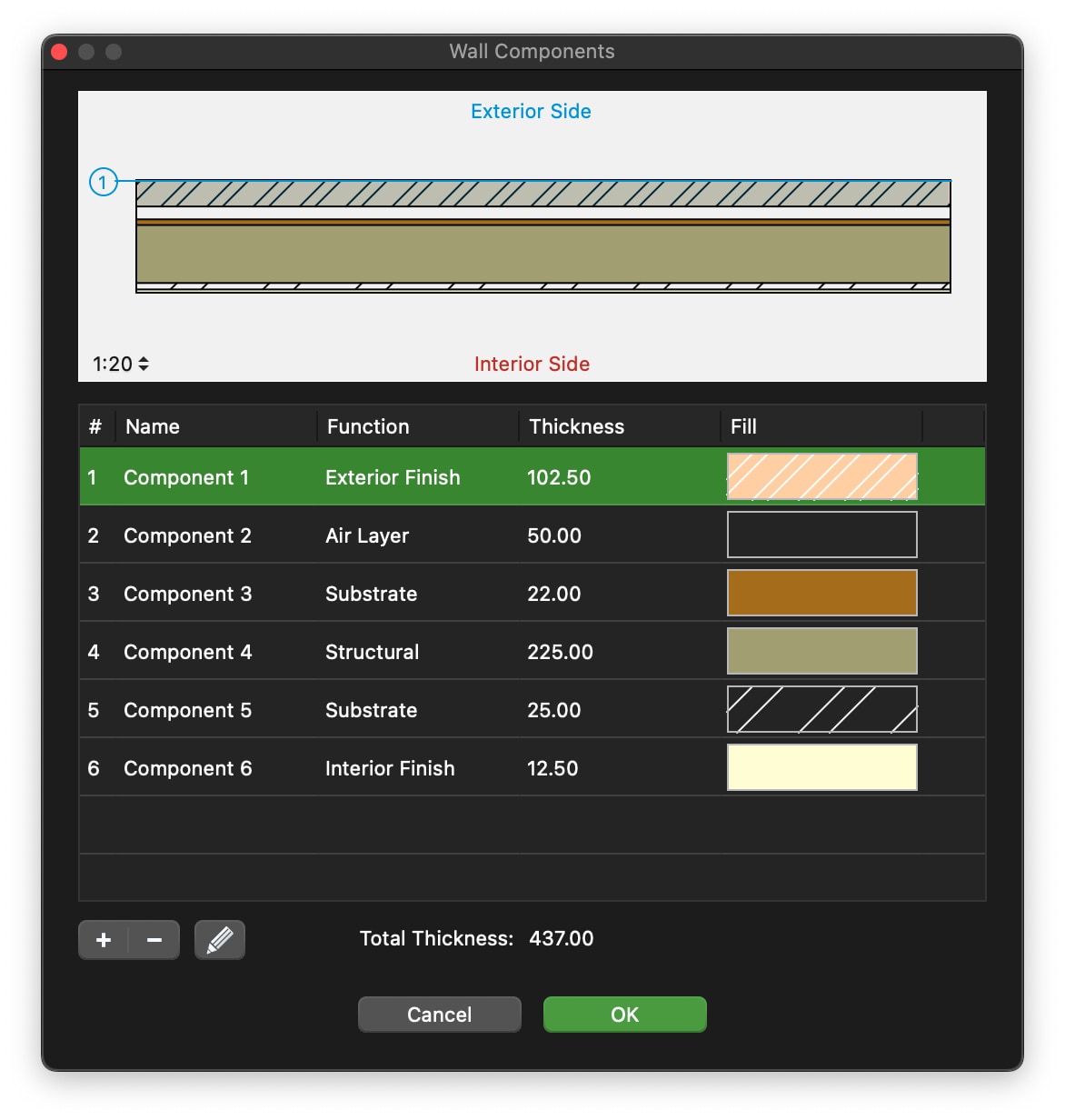
Wall Components Window
Use this window to set and edit the components of a compound wall.
The table lists the components of the wall from the exterior side to the interior, with a progressive index number. The selected component is highlighted in the preview, which shows the current wall at the scale set in the lower left corner. You can check how the wall is rendered at the different drawing scales by using the drawing scale menu.
 _
_
The total thickness of the wall is computed on the sum of the single components and shown at the bottom of the Thickness column.
You can add, remove and reorder the components, and rename a component by double- clicking its name. Use the + button to add a new component and the - button to remove the selected component in the table. Adding a new component opens immediately the properties editor. To edit a component, click the Edit icon on the right.
The properties of a wall component are:
- Function: each component has its own function which can define its behavior and appearance. The available functions are: Exterior and Interior Finish, Thermal Film, two kinds of Thermal Insulation, Air Layer, Substrate, Structural, Membrane. There can only be one exterior and one interior finish. The (batting) Thermal insulation component is always rendered with the Insulation line type.
- Thickness, in the current drawing units;
- Fill color, hatch, hatch color and hatch scale.
Click the Cancel ✖ or OK ✔ buttons to cancel or confirm the changes to a component and return to the list of components. The + button confirms the current component and creates a new one.
Construct and Edit Walls
Construct and Edit Walls
To draw a wall, click to set its start point, move the cursor and click again to set its endpoint: walls are connected like poly-lines. Walls have their construction side and the “Exterior side” property, marked with a blue line, to consider when inserting openings: to change the leading side while drawing, click on the Option menu close to the last vertex. Press the Alt key to invert the exterior side while moving the cursor.
 _
_
A compound wall can be inserted by its structural component: choose between exterior, interior sides and middle line to easily align your walls to the structural grid.
To edit a wall, select it and move, stretch, shorten it with the Arrow tool or change its parameters numerically via the Object Info panel.
Edit a Wall with the Object Info Panel
The Point section of the Object Info panel enables the changes of the coordinates of the three control points of the selected wall: use the arrows to select the active point and the fields to enter the new coordinates.
The Geometry section displays the following options:
- Length and Width fields to change its geometry;
- Leading side buttons to change the construction axis of the wall (this option can shift the selected wall accordingly);
- Invert Sides to invert Interior/Exterior side of the wall (this can invert the opening direction of windows and doors inserted in the selected wall).
The ID section shows the wall Name, Tag and Description fields to add information to the selected wall and provides the Settings button to open the Wall Settings window.
The Tools menu and the contextual menu provide two commands specific for walls: Convert to Wall and Rebuild Wall.
Standard-Case Walls
Standard-case walls have one uniform component and its representation can be a solid color fill, a hatch, or a combination of the two. The geometry can be rectangular, with a constant thickness from start to end point, or polygonal, with variable thickness from start to end.
_
Basic walls automatically join to other basic walls, regardless of thickness and fill, unless the joints are disabled in the Settings window.
Standard-Case Wall Settings Window
- Type pop-up window and New Type icon.
- Family, Basic or Compound
- Geometry and Thickness, in the current unit: selecting the option of variable thickness enables the end thickness field.
- Leading side and Exterior side: select the construction side of the wall. You can also access this option by clicking the pop-up menu icon during the construction the wall. The option to invert the interior and exterior faces of the wall allows to switch the sides of the wall. The exterior side is highlighted in blue when drawing and selecting walls. Wall Joints options. Deselect an option to disable the automatic connection of new walls or to unlink an existing wall.
- Border attributes: Line type and pen weight.
- Fill attributes: solid color, hatch type and color, hatch scale.
Utilities for Walls
Convert to Wall
Convert To Wall applies to lines, polygons, arcs and curves. This function converts those objects into walls with the current settings: select the items to convert and then choose Tools ▸ Walls ▸ Convert To Wall on the Tools menu. This command is also available as a button in the Edit Tool Bar.
Rebuild Wall
Use this command to regenerate the geometry, side intersections and nodes of one or more walls. This is especially useful in situations in which a node needs to fixed.
The Rebuild Wall tool can either be applied to selected walls, or to multiple walls in one run by clicking on them.
To use it on the selection:
- Select the walls you want to rebuild;
- Choose Tools ▸ Rebuild Wall or open the radial menu and choose Rebuild Wall fromthe Tools submenu.
To apply it to multiple walls:
- Choose Tools ▸ Rebuild Wall or open the radial menu and choose Rebuild Wall from the Tools submenu.
- Click once on each wall to rebuild
- Click on a void part or on another object to end.
Wall Tool Settings
Walls are parametric elements of the building that can have several different properties such as sizes, options, functions and compositions that define a wall type. Use the Wall tool settings window to define the parameters of the wall type.
_
Wall Family
You can select to create a standard-case (basic) wall or a composite wall.
Standard-case Walls
When you select standard-case walls, you can select its geometry as regular or irregular. Regular walls are defined by one thickness value and their shape in plan view is rectangular.
Irregular walls are defined by start and end thickness values.
Basic walls automatically join to other basic walls, regardless of thickness and fill, unless the joints are disabled in the Settings window.
Composite Walls
Composite walls consist of multiple layered components, each with its own properties. Composite walls can only be rectangular in shape, with constant thickness from start to end. The total thickness is calculated as the sum of all the internal components.
_
When you select the Composite Wall family in the Settings panel, the family-specific section shows a button to edit the internal components, the value of the total thickness calculated as the sum of the internal components, and the pen wight menu to define the pen to be used for the lines that separate the internal components.
- Composite walls can have any number of internal components, and you can add, remove, reorder and edit the components at any time through the Wall Components window.
- By default, basic walls and compound walls do not join automatically, because they are different elements that would not be joined in a real situation. Also, they are made of different materials which would not match. However, if a particular situation requires it, you can choose to activate the Allow Joints options and attempt to join two walls of different type.
_
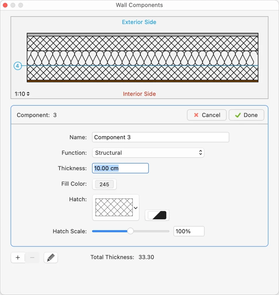
Editing Composite Wall Components
Press the Edit button on the Wall tool settings window to open the Wall Components panel. This panel allows you to define, reorder and edit the internal components of the current wall type.
_
The table lists the components of the wall from the exterior side to the interior, with a progressive index number. The selected component is highlighted in the preview, which shows the current wall at the scale. You can check how the wall is rendered at the different drawing scales by using the drawing scale menu on the preview area.
The total thickness of the wall is computed on the sum of the single components and shown at the bottom of the Thickness column.
You can add, remove and reorder the components, and rename a component by double-clicking its name. Use the + button to add a new component and the - button to remove the selected component in the table. Adding a new component opens immediately the properties editor. To edit a component, click the Edit icon on the right.
 _
_
Use Component panel to enter the component name, function, thickness and the hatch to be used in horizontal and vertical sections.
Click the Cancel ✖ or OK ✔ buttons to cancel or confirm the changes to a component and return to the list of components. You can also push the + button to confirm the current component and create a new one directly without going back to the components list.
Doors
Doors are, like Windows, architectural elements that belong to the Openings class and in their most basic function are used to open holes in walls. Openings are hosted elements in that they can only be placed in a wall that acts as the host element.
Like any other architectural element, doors have geometric, graphic and information parameters that you can edit through the settings window and the Object Info panel.
Topics in this section
Subsections of Doors
Door Tool Settings
To open the tool settings of doors, select Edit ▸ Settings Window ▸ Door… or double-click the tool icon. You can load an existing Door Type if available or customize the door by selecting its family and setting all the parameters and options. Current settings can be saved as new types by pressing the Add icon.
The Door tool settings window includes two panels: Geometry and Options.
_
Door Geometry
Use this panel to configure the parameters that define the shape and size of the door, such as width, height, reveal type, etc. The panel is provides the following options:
- Family. Open the drop-down menu to select the door family from the list. The available families include:
- empty opening
- simple door, a symbolic representation of a door
- swinging doors
- bypass sliding doors
- surface sliding doors
- pocket doors
- folding doors
_
Door Options
Use this panel to specify the dimensions of the frame, opening directions, the optional sill and various display options.
 _
_
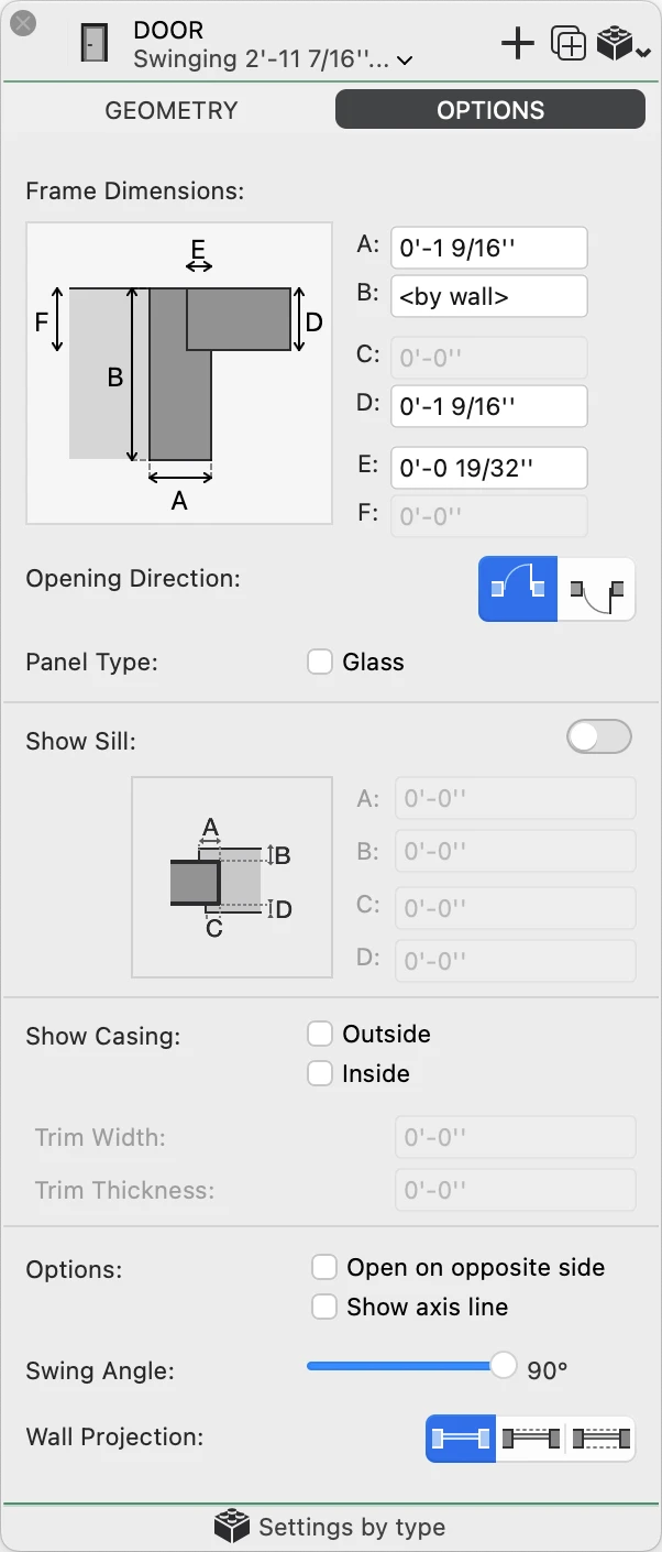
Door Options
Use this panel to specify the dimensions of the frame, opening directions, the optional sill and various display options.
- Frame Dimensions. Depending of the current reveal, you can specify the dimensions of the various components of the door frame.
- Opening Direction, outward or inward.
- Panel type. Select Glass to add a glass to the internal panel of the door.
- Show Sill. Activate the switch to enable the controls and define external and internal offsets and widths of the sill.
- Show Casing. Depending on the desired level of detail, you can choose to display the outside and inside casing component and specify its dimensions.
- Display Options:
- Select Open on opposite side to flip the opening direction.
- Show an axis line on the middle of the opening.
- Define the angle at which swinging door are displayed, ranging from 0° (closed door) to 90° (fully open).
- Wall Projection. Choose whether to display one, two or no projection lines of the host wall.
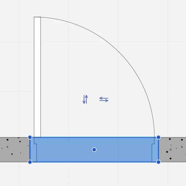
Editing a Door
You can resize, move and flip a door directly by clicking one of its control points. All editing operations are available when the door is selected, but the flip operations are only available when the door is the only selected object.
 _
_
Resize a Door
To resize a door, click one of its handles at the start or end sides and move the pointer. Pop-up dimensions show the current size. You can enter a new size value or click to end the editing operation.
Move a Door
Click its middle handle to move the door within its wall.
Flip a Door
Click the double arrows to flip the opening direction, outside or inside, and the swing side, left or right.
Edit a Door with the Object Info Panel
You can also use the Object Info panel to resize the door.
The Geometry section displays the Rough Width and Nominal Width fields to change the size of the selected door.
The ID section shows the Name, Tag and Description fields to edit or add information to the selected door: use the Settings button to open the Door Settings window for specific editing options.
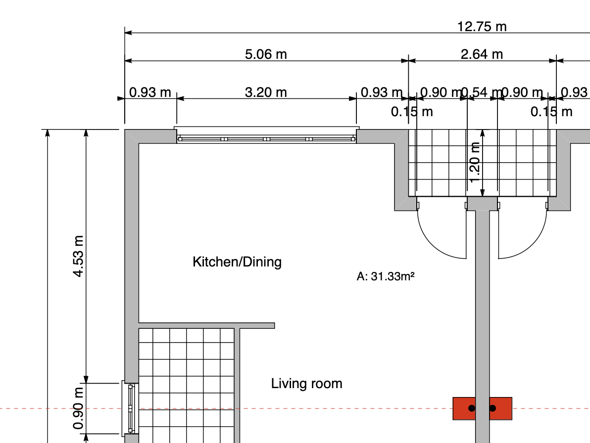
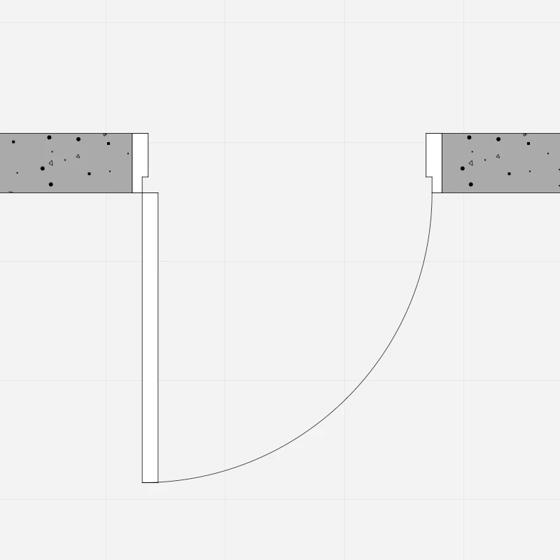
Insert a Door
To insert a door in the project follow the steps below:
- In the Settings window load the Type if available or select the family of the opening;
- Alternatively, define custom door settings;
- In the Project window set the position of the opening by clicking on the wall;
- Click the internal / external area of the wall to choose the opening direction;
- For single doors (swinging, sliding, pocket or folding doors) click on the wall to position the door, then click in the desired quarter of the region described by the cartesian axes to set its opening or swinging side. As you move the cursor over a wall, temporary dimensions show the relative distances of the door from the surrounding vertices or joints of the wall. As for windows, to set and constrain the value of either dimension, so that the opening is exactly at that distance from a reference point, enter the value on the keyboard and move the pointer, so as to choose which dimension on either side of the wall the value applies to. Click to confirm and insert the opening.
Windows
Windows are architectural elements that belong to the Openings class and in their most basic function are used to open holes in walls. Openings are hosted elements in that they can only be placed in a wall, that acts as the host element.
Like any other architectural element, windows have geometric, graphic and information parameters that you can edit through the settings window and the Object Info panel.
Topics in this Section
Subsections of Windows
Editing a Window
You can resize, move and flip a window directly by clicking one of its control points. All editing operations are available when the window is selected, but the flip operations are only available when the window is the only selected object.
Resize a Window
To resize a window, click one of its handles at the start or end sides and move the pointer. Pop-up dimensions show the current size. You can enter a new size value or click to end the editing operation.
Move a Window
Click its middle handle to move the window within its wall.
Flip a Window
Click the double arrows to flip the opening direction, outside or inside.
Editing a Window with the Object Info Panel
The Geometry section displays the Rough Width and Nominal Width fields to change the size of the selected window.
The ID section shows the Name, Tag and Description fields to edit or add information to the selected window: use the Settings button to open the Window Settings dialog.
The Opening Direction of a window can be changed through the Settings window: select the window, open the Options pane of Settings and select Opening Direction > “Open Inside” or “Open Outside”.
Insert a Window
To insert a window in a wall, activate the Window tool in the Toolbox and do the following:
- In the Settings window load the Type if available or select the family of the opening.
- Enter the desired window settings.
- In the Project window set the position of the opening by clicking on the wall.
- Click above or below the wall to choose the alignment side of the window.
As you move the cursor over a wall, temporary dimensions show the relative distances of the opening from the surrounding vertices or joints of the wall.
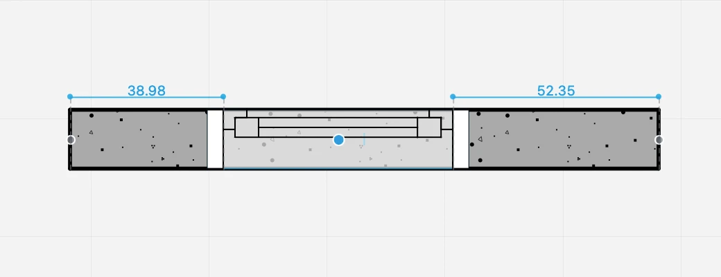 _
_
To set and constrain the value of either dimension, so that the opening is exactly at that distance from a reference point, enter the value on the keyboard and move the pointer, so as to choose which dimension on either side of the wall the value applies to. Click to confirm and insert the opening.
Window Tool Settings
To open the tool settings of windows, select Edit ▸ Settings Window ▸ Window… or double-click the tool icon. You can load an existing Window Type if available or customize the window by selecting its family and setting all the parameters and options. Current settings can be saved as new types by pressing the Add icon.
The Window tool settings window includes two panels: Geometry and Options.
Window Geometry
Use this panel to configure the parameters that define the shape and size of the window, such as width, height, reveal type, etc. The panel is provides the following options:
- Family. Open the drop-down menu to select the window family from the list. The available families include:
- empty opening
- generic and simple windows, symbolic representations of a window
- casement windows
- single/double -hung windows
- sliding windows
_
Window Options
Use this panel to specify the dimensions of the frame, opening directions, the optional sill and various display options.
 _
_
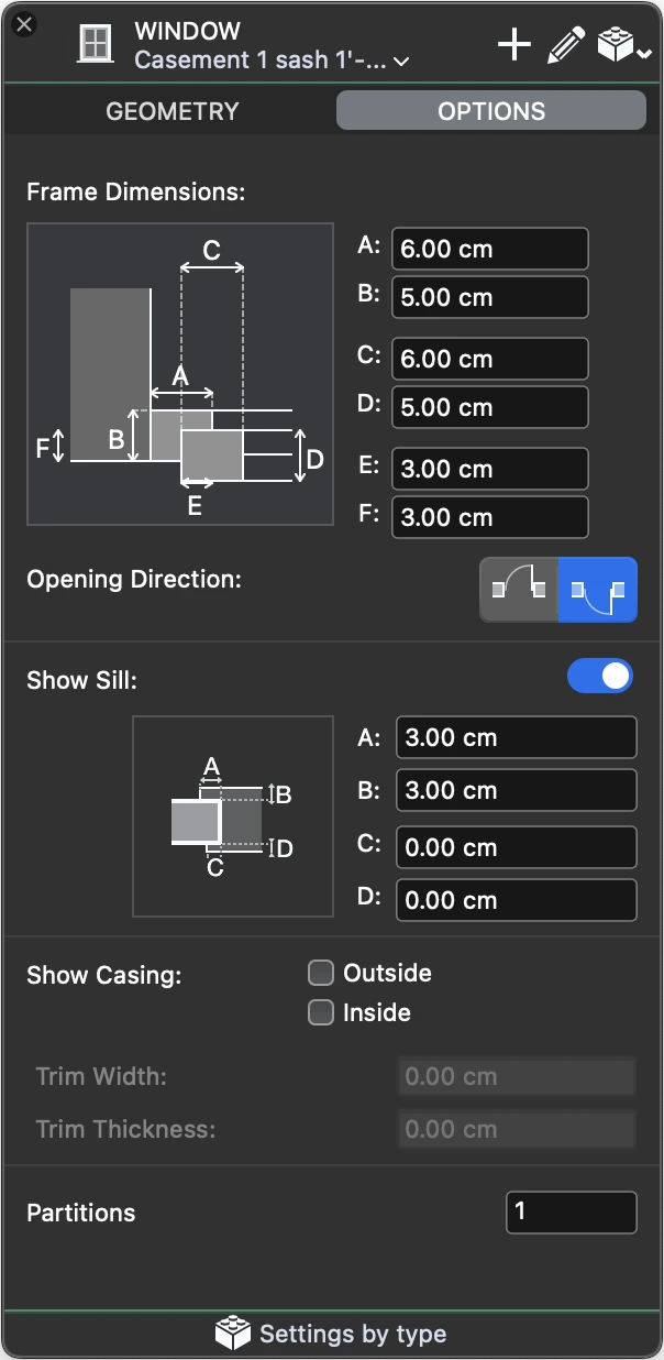
Window Options
Use this panel to specify the dimensions of the frame, opening directions, the optional sill and various display options.
- Frame Dimensions. Depending of the current reveal, you can specify the dimensions of the various components of the door frame.
- Opening Direction, outward or inward.
- Show Sill. Activate the switch to enable the controls and define external and internal offsets and widths of the sill.
- Show Casing. Depending on the desired level of detail, you can choose to display the outside and inside casing component and specify its dimensions.
- Partitions: specify the number of internal partitions of the window.