Zones
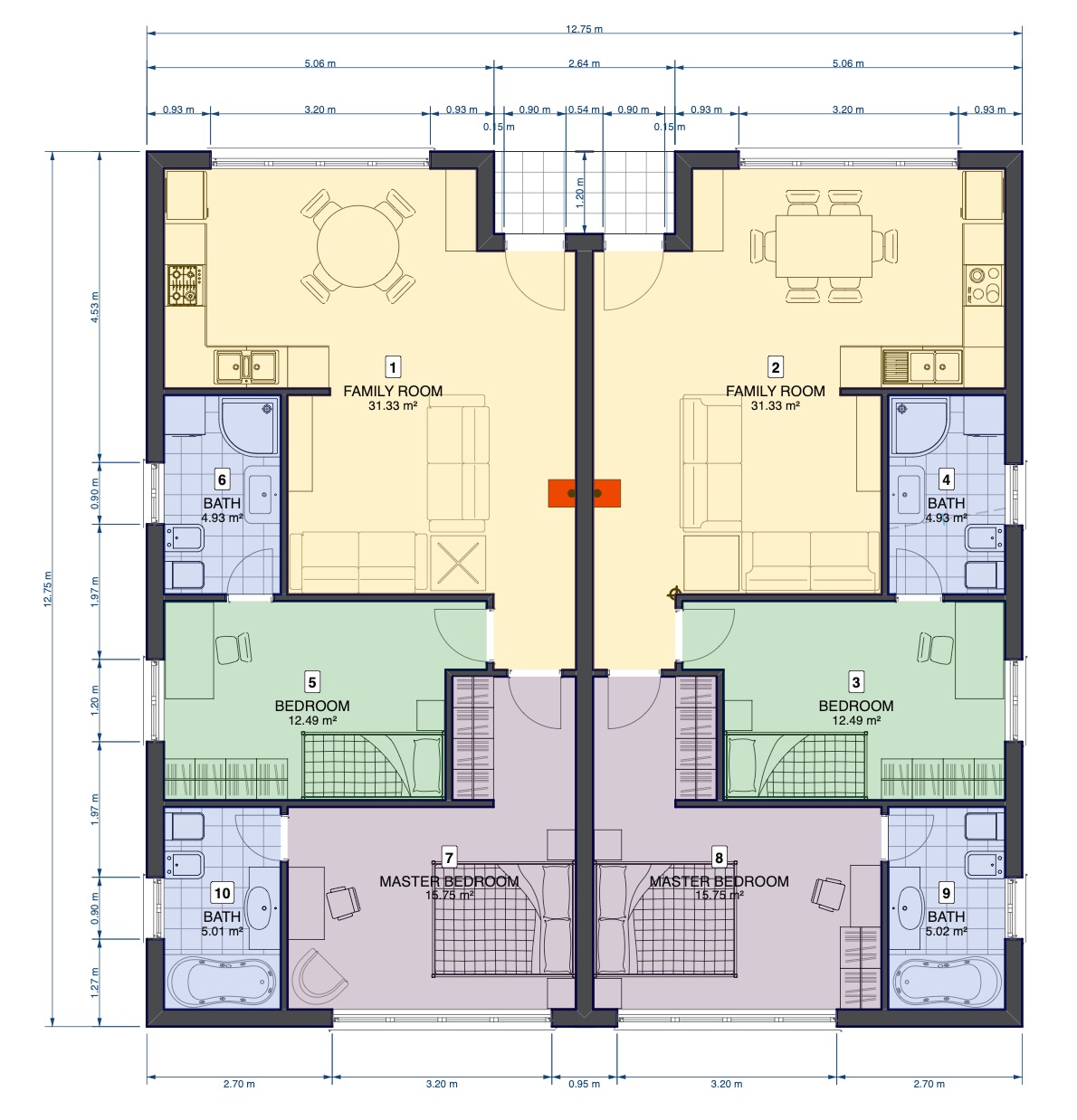
Zones are subdivisions of space identified by their function. Zones typically represent rooms in a floor, wings of a building, or areas in landscape design and city planning.
A zone is identified by a unique number, a name and a color.
Info
Zones are computable entities and their properties like layer, name, id, area, etc. are available when you create a schedule that includes the zones of a project.
Topics in this section
Subsections of Zones
To access the Zone tool settings, choose Edit ▸ Settings Window ▸ Zones or double click the tool icon on the Toolbox.
The Zone settings windows includes two panels: Zone Settings and Names and Colors.
Zone Settings
The Zone Settings panel is organized into two sections, Zone Id and Label.
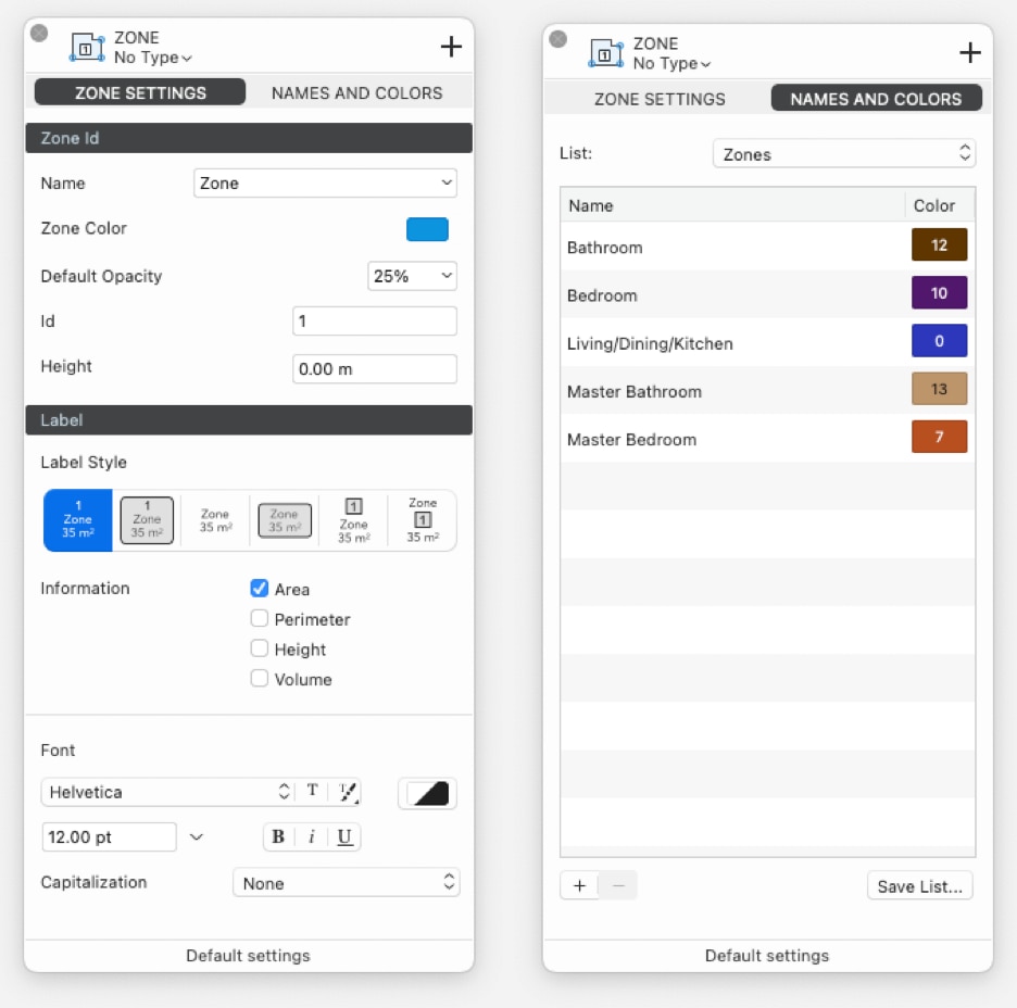
Zone Id
- The Name menu to choose a name from a pre-defined list: the selected names are added in the top most section of the list as Active List of the current project.
- The Zone Color menu opens the Palettes window to select a color. The Zones palette below the Standard HighDesign palette offers 16 pre-defined colors: if there is no choice, the colors are automatically assigned from the Zones palette starting from the first one of the Zones palette.
- The Default Opacity option is set as 25%: the Opacity control allows to set a different value.
- The Id is automatically set in a growing numbered order starting from the firstly created zone.
- The Height option allows to set an average height of the zone in order to get a computed volume in schedules.
Zone Label
The Label section of the Zone Settings panel provides all the options that define the style of the label, or stamp, of the zone and the information displayed in it:
- Label Style, with six different border and style alternatives.
- Information, to select one or more of the following information to be displayed in the label: Area, Perimeter, Height, Volume.
- Font, which offers all the font, color, size, style and capitalization options of the text label of the zones.
Names and Colors
The Names and Colors panel displays the current zone Active List of the project with the names and associated colors. Lick name or color button to make changes.
The List menu provides the default zone lists available in the HighDesign Library, the saved lists available in the User Library or the current list in the Project.
The Save List button allows to save the current list in the User Library to be available in new projects.
Use the “+” and “-“ buttons to add new zones to the list or to delete the selected zone.
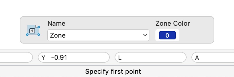
The floating window in the bottom of the drawing window allows the quick selection of the Name and Color properties of a new zone or those changes of the selected zone: it shows up when the Zone tool is active only.
Creating Zones
To create a zone, activate the Zone tool in the Design section of the Toolbox.
The Zone tool has three construction methods: Polyline/Automatic, by Rectangle, and by Rotated Rectangle.
Define the combination of name and zone color before the insertion.
You can define the combination of name and fill color of the next zone before its insertion in two ways:
Zone by Polyline/Automatic Room
With the Zone By Polyline method you can create a zone in two ways:
- Manually by specifying the points of its outline, or
- Automatically by clicking inside a room defined by walls.
To create a room by automatic detection
- Move the pointer over the floor plan. The tool detects rooms enclosed by walls and automatically prepares a zone with default settings.
- Click to confirm the zone. The position of the label is also defined automatically as the center of the polygon and can be modified later once the object is created.
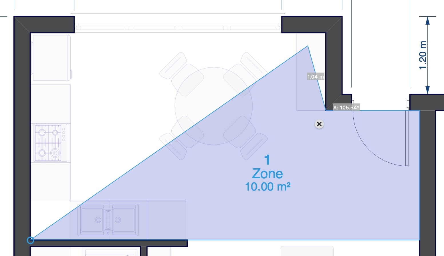
To create a zone by polyline
When no enclosing walls are detected, you can create a zone by defining its shape as a polyline by clicking anywhere on the drawing.
- Click to specify the first point of the polyline.
- Click to specify the next points of the polyline.
- Click on the start point or double click to end the sequence and create the zone.
Tip
Alternatively, even when enclosing walls are detected and a room is automatically generated, you can still define a zone by polyline by holding down Cmd (Mac) or Ctrl (Windows) and clicking to specify the first point.
Zone by rectangle
- Specify the start point of the rectangle.
- Move in any direction and click to specify the opposite point of the rectangle.
Zone by rotated rectangle
- Specify the start point of the rectangle.
- Move in any direction and click to specify the base and rotation of the rectangle.
- Move the pointer and click to specify the height of the rectangle.
Edit Zone Polygon
The boundary of a zone is a 2D polygonal shape that can be edited by moving, adding and deleting vertices, and can be modified with the commands that apply transformations, such as Move, Rotate, Scale, etc.
All editing actions apply to the selected object.
Move a vertex
- Click the vertex and move the pointer to the desired location.
Move a side
- Click the mid-point between two vertices to move the side of the polygon.
Add a vertex
- Hover the pointer on a vertex to open the Zone pop-up menu and select “Add Vertex”. Alternatively, click the desired location of a side of the zone when the “+” sign shows up to add a vertex.
Delete a vertex
- Hover the pointer on a vertex to open the Zone pop-up menu and select “Delete Vertex”. Alternatively, move a vertex to another one till the “-“ sign shows up to delete that vertex.
A zone behaves like a graphic object, therefore other graphic transformations such as Move, Rotate, Mirror, Scale, etc. are applied as in all other graphic entities.
To change name, id, color and label of a zone, select it and use the Object Info or open the Zone Settings window.
When the Zone tool is active, a floating window on the bottom of the drawing area allow quick changes of zone name and color of the selection.
Convert to Zone
You can convert poly-lines, polygons, rectangles, hatches/fills to zones through the “Convert to Zone” command on the Tools menu, also available via the Contextual Radial menu.
This command applies to the selected object.
Supported objects
The classes of graphic object that you can convert to zones are:
- Rectangles;
- Polygons;
- Poly-lines, even those with curved sides (concave or convex arcs);
- Hatches and Fills.
The new zone will get the color either from the fill of the selected object (if that object has a fill) or from the default color of the Zone palette. You can change color and label at any time.