Subsections of Dimensions
About Dimensions
Use the Dimensions Tool to insert linear, multiple linear, radial, angular, ordinate and elevation dimensions. To set the dimension properties, either double-click the Dimensions tool in the Drawing Tools bar or choose Edit ▸ Settings Window ▸ Dimension to open the Dimension Settings dialog.
You can create a variety of dimensions for many different object classes. There are five dimension types:
- Linear, single and multiple, measure the linear distance between two points.
- Radial, that measure radius and diameter of arcs and circles.
- Angular measure the angle between to segments.
- Ordinate dimensions measure progressive distances or heights from a start point.
- Elevation dimensions mark a point at a given elevation.
Topics in this section
Angular Dimensions
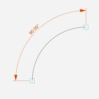
Angular dimensions measure the internal angle of an arc or the angle between two linear segments.
 _
_
To create an angular dimension
- Select the Angular dimension tool. Make sure the Associative option is selected if you want the dimension to automatically adjust to the measured object.
If you are measuring an arc:
If you are measuring an arc:
Dimension Tool Settings
Use this panel to set and edit the parameters of dimension objects. The Dimension tool settings window is includes two panels, Text and Graphics.
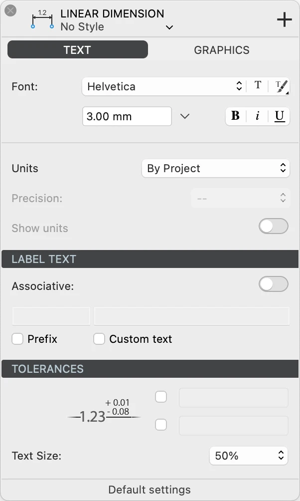
Dimension Text Settings
This panel contains all the settings that control the text label that displays the dimension value. You can set the font style, choose the measurement units, add a prefix and enter a custom text, and specify any tolerances.
 _
_
Text Font and Units
- Text font: use the menus and buttons to choose the desired font face, text size (at 1:1), and apply a character style. In HighDesign Pro you can also choose a text Style from one of the resource libraries.
- Units: you can have the dimension value expressed in the current sheet’s units, or specify a custom unit and precision. You can also choose to show or hide the unit symbol.
Label Text
Use this section to enable the associative dimension and to enter a prefix and a custom text.
- Associative dimensions are associated to the object they measure and adjust to its geometric changes so that the dimension is up to date all the time.
- Prefix: enable the option and enter a text to be displayed before the dimension value.
- Custom text: enable this option to replace the dimension value with a text.
Tolerances
A dimension label can show tolerance values that define a range within which the measurement is considered valid. This is commonly used when dimensioning parts and components that require particular precision so that the manufacturing machines can be calibrated.
You can choose to enable only the upper tolerance, the lower tolerance, or both. Enter exactly the text that you want to be displayed, for example “+ 0.01” or “- 0.02”.
Tolerances can be displayed with a smaller font size than the dimension label. Use the popup menu to select a value relative to the current font size. For example, if the label font size is 16 points, a value of 75% means that the tolerances will be displayed at 12 points, a value of 50% means 8 points.
Dimension Graphics
Use this panel to define the arrow shape and size, the type of extension lines, gaps, and more.
Arrows
Open the pop-up menu to select an arrow or marker type.
The available types for linear, radial and angular dimensions are:
- None
- 15° arrows in the open, outline, filled and filled with extension variations
- 22° arrows
- 30° arrows
- 45° arrows
- architectural tick markers
- outline and filled circle
- outline and filled square
- outline and filled diamond
- half arrows
The marker types for elevation dimensions are:
Use the text field to specify the arrow or marker size in the current units at 1:1.
Label
Select the position of the text label relative to the dimension line. Choose above, middle or below the line. Positions above and below the dimension line also allow to specify a gap between the line and the text.
A fourth label position locks the label in the most readable position and orientation, that is above and to the left of the dimension line.
Labels can optionally have a border around the text to improve their visibility.
You can select a label orientation from the available options:
- Aligned, readable. A label will have the same angle as the dimension line and will always be readable, even when the dimension line has been rotated or flipped.
- Aligned: the label follows the angle of the dimension line.
- Horizontal: the label is always displayed horizontal even in aligned dimension lines.
Another option let you flip the text relative to the direction of the source points.
Elevation Dimensions
This method can be used to add elevation dimensions to your project.
To create elevation dimensions, set the “zero” datum, that is the Absolute Origin, and click on the points you need to measure. All dimensions will display values relative to the origin; if you move the origin, all other dimensions will change their values accordingly.
Linear Dimensions
This method is used to insert linear dimensions between two points. The dimension line can have a generic angle or can be axis-aligned and display the dx or dy distance with absolute values.
_
Linear dimensions can be independent or associative (SE/Pro). Independent dimensions are defined by the two source points. Modifying the measured object does not affect the geometry and value of the dimension. Associative dimensions are linked to their source element and update their geometry and value automatically as the source object is moved or modified. Dimension and object can reside on different layers.
Create a non-associative dimension
- Click on the source points and move the pointer to place the dimension line.
- If you move vertically or horizontally (following the guide lines that appear on screen) you create a vertical or horizontal dimension; otherwise, the dimension will be object-aligned.
Create an associative dimension
- Activate the Associative option, either in the Settings window or by clicking the Associative Dimensions button on the Properties toolbar, next to the Dimension methods.
- Click the source object. Associative dimensions must be defined by clicking between two vertex points since they require only the definition of the source object.
- Define the height of the witness line, i.e. its distance from the source object.
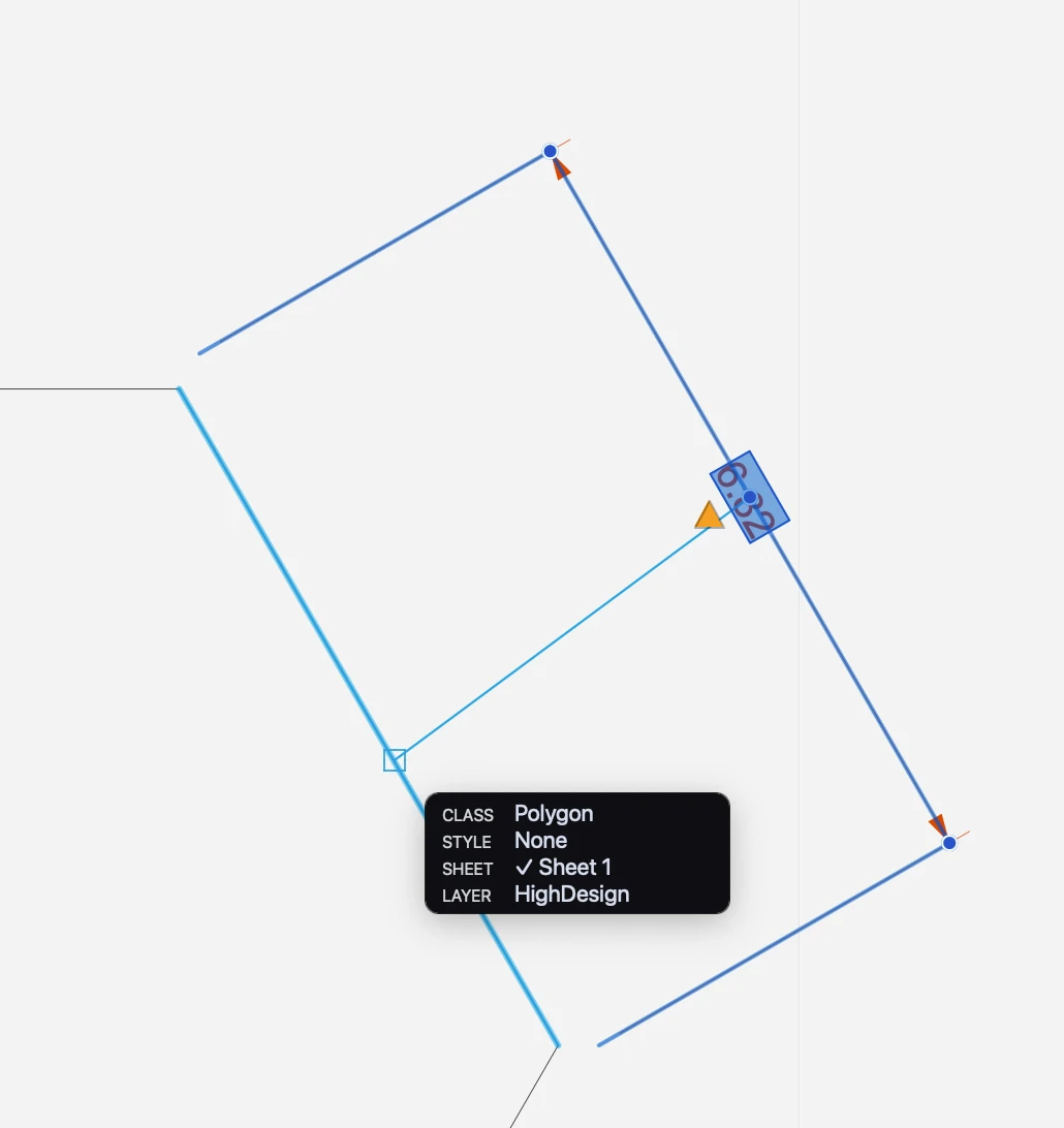
Associative dimensions are marked with squares on the source points. These squares are only visible on screen and are not printed nor exported.
_
Associate a Dimension
An independent dimension can be changed into an associative dimension, and vice-versa. To change the associative behavior of a dimension, select it and press the Associative switch on the Dimension Settings.
 _
_
When an independent dimension becomes associative, it lacks the link to an actual source object. Also, deleting or otherwise removing the source object can cause the relative dimension to lose its link. When an associative dimension does not have its source object, or is not able to find it, the square marks are no longer visible and a yellow “caution” triangle appears near the mid point of the witness line. An unlinked dimension can be re-associated to its source object or a new element in two ways:
- Using the command Tools ▸ Associate Dimensions/Annotations. Either select the dimension to link and begin the command, or begin the command and the click on the dimensions. With this method, it is possible to associate more dimensions in one run of the command. When you click on the dimension, a line is drawn from the mid point of the dimension to the cursor. Click on the new source object or element to link the dimension.
- Using the caution triangle. Select the dimension and click the yellow triangle of an unlinked dimension to begin the Associate Dimension command. The procedure is then the same as described above.
Multiple Linear Dimensions
This method allows you to create horizontal or vertical aligned dimensions (dx or dy distances) of two or more progressive points. Once the first segment is defined, all following dimensions will keep the first alignment and height.
Multiple linear dimensions can be of two types: continued and baseline.
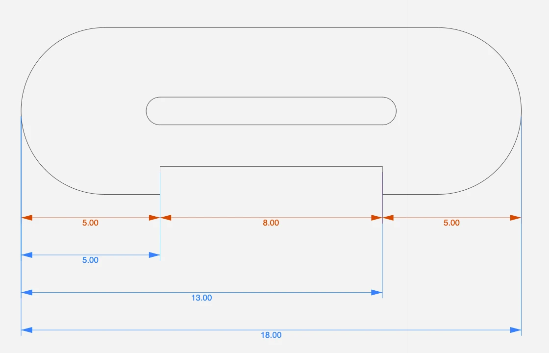
Continued dimensions
Continued dimensions measure points in a linear progression. Each dimension measures the section from the previous point to the next.
Create continued dimensions
- Activate the Multiple Linear Dimensions tool.
- On the Properties bar, make sure the current mode is set to Continued.
- Click to specify the start point.
- Specify the end point. Start and end points do not need to be aligned.
- Define the first dimension line, either aligned to the source points, horizontal, or vertical. The first dimension line defines alignment and height of the successive dimensions.
- Click to specify the next end point. Each new dimension uses the end point of the previous dimension as start point.
- Double click or cancel to end the operation.
Baseline dimensions
Baseline dimensions measure progressive distances from a base point. Each dimension line is placed at an increasing offset from the source points and measures the total distance of the end point from the global start point.
Create baseline dimensions
- Activate the Multiple Linear Dimensions tool.
- On the Properties bar, select the mode to Baseline.
- Click to specify the base point and define the first dimension line.
- Click to specify the next end points. Each new dimension is placed at an offset from the measured objects that is a multiple of the height of the first dimension.
- Double click or cancel to end the operation.
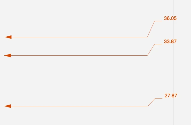
Ordinate Dimensions
With this method you can calculate the perpendicular distance from an origin point. The origin is identified with the Absolute Origin of axes. Distances along the x- and y-axes to objects to measure are specified using extension lines, with the distances indicated numerically at their ends with text labels.
 _
_
Set the Origin and click on the points to measure: move the pointer parallel to the X axis to get the Y distance and parallel to the Y to get the X distance. If you change the origin, Ordinate dimensions will be updated automatically.
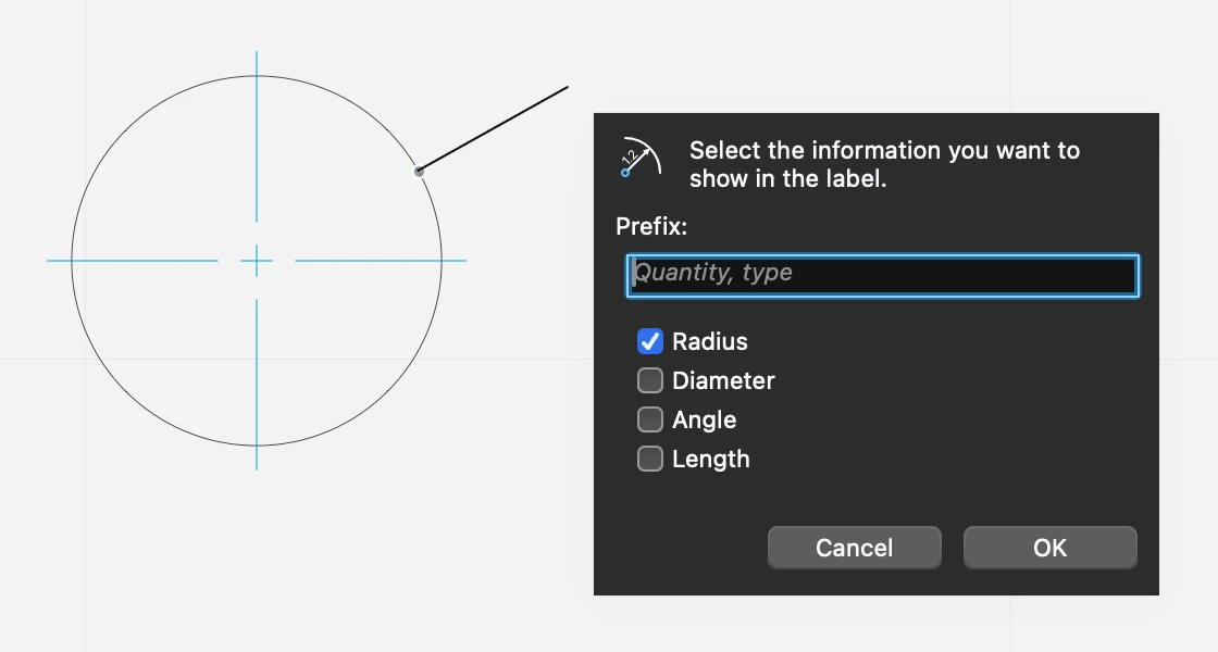
Radial Dimensions
Radial dimensions measure the radius, diameter, internal angle and length of arcs and circles.
_
To create a radial dimension
- Select the Radial dimension tool. If you want the dimension to be associated to the measured arc or circle so that it is always updated, make sure the Associative option is set.
- Click on a circle or arc
- Move the pointer inside or outside the arc or circle to define the position of the dimension
- As you click, a pop-up dialog lets you choose the type of information that you want the radial dimension to display. The available options are:- 5. Prefix: enter any text that you want to display before the values6. Radius of the circle7. Diameter of the circle8. Angle of the arc9. Length of the arc or circumference of the circle
 _
_
To edit a radial dimension
Select the radial dimension, then
- Click its start point on the circle to move it along the circle
- Click the end point to adjust its orientation
- Click the label to open the pop-up dialog and edit the displayed information
By default, associated radial dimensions show center marks or lines on measured arcs. To hide the center lines, uncheck the Show center marks on the Dimensions settings window when the radial dimension object is selected.