Chapter 1
Subsections of Walls
About Walls
The Wall tool allows the creation of walls which are parametric objects, automatically connected on their vertices and borders. To set the attributes, double-click the Wall Tool icon or select Edit ▸ Settings Window ▸ Wall… to open the Wall Settings dialog.
Walls are host elements, in that certain elements like doors and windows can only be inserted in a wall.
Walls are classified into two families: Standard-case Wall, made of one, uniform component, and Composite Wall, made of different internal components.
 _
_
Topics in this Section
- Wall tool settings
- Standard-case Walls
- Composite Walls
- Construct and Edit Walls
- Utilities for Walls
Compound Walls
Compound walls consist of multiple layered components, each with its own properties. Compound walls can only be rectangular in shape, with constant thickness from start to end. The total thickness is calculated as the sum of all the internal components.
_
- Compound walls can have any number of internal components, and you can add, remove, reorder and edit the components at any time through the Components window.
- By default, basic walls and compound walls do not join automatically, because they are different elements that would not be joined in a real situation. Also, they are made of different materials which would not match. However, if a particular situation requires it, you can choose to activate the Allow Joints options and attempt to join two walls of different type.
- Compound walls can use one pen weight for both borders and internal divisions, or you can assign a pen weight for the outer borders, and one for the internal components.
_
Compound Wall Settings Window
- Type pop-up window and New Type icon. This window lists all the available Types, of both basic and compound families. It is advisable to enter descriptive names when saving a new wall type.
- Wall Family.
- Components section:
- Edit Components button to access the Components window; use this button set the components of a new wall or edit an existing wall.
- Total computed thickness; the sum of thickness of the internal components determines the total thickness of the wall.
- Internal pen weight of components. The pen weight can be Same As Borders to set the same pen weight as that used for the borders of the wall, or one of the available pen weights.
- Leading Side: see Basic Wall Properties Window for the description.
- Wall Joints options: see Basic Wall Properties Window for the description.
- Border line type and pen weight. Internal components can only have a continuous line division.
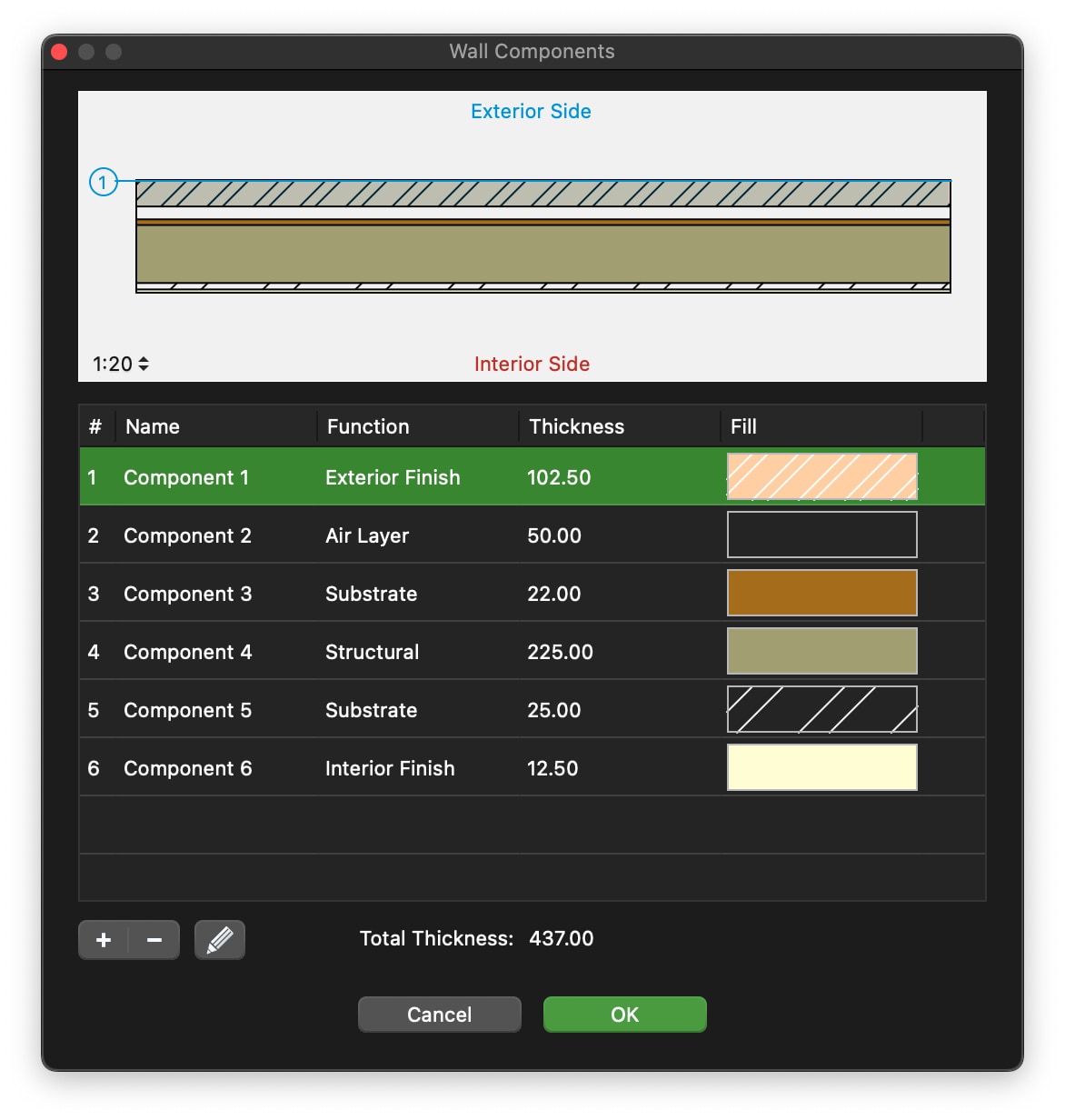
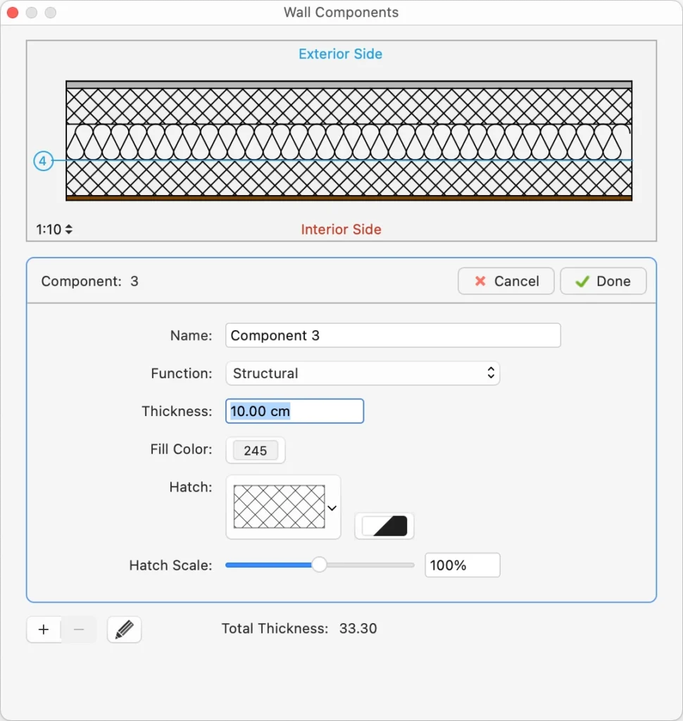
Wall Components Window
Use this window to set and edit the components of a compound wall.
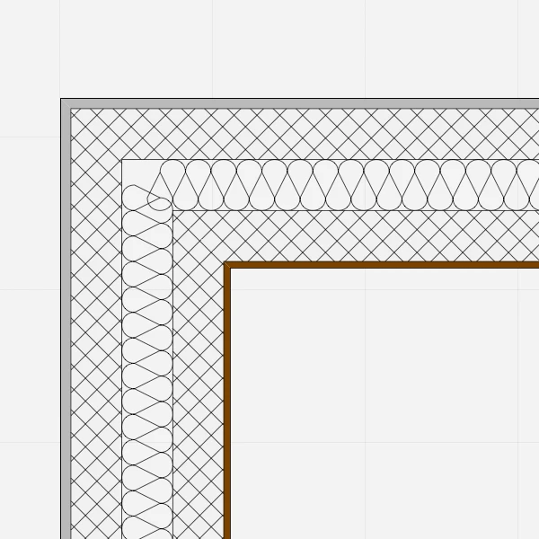
The table lists the components of the wall from the exterior side to the interior, with a progressive index number. The selected component is highlighted in the preview, which shows the current wall at the scale set in the lower left corner. You can check how the wall is rendered at the different drawing scales by using the drawing scale menu.
 _
_
The total thickness of the wall is computed on the sum of the single components and shown at the bottom of the Thickness column.
You can add, remove and reorder the components, and rename a component by double- clicking its name. Use the + button to add a new component and the - button to remove the selected component in the table. Adding a new component opens immediately the properties editor. To edit a component, click the Edit icon on the right.
The properties of a wall component are:
- Function: each component has its own function which can define its behavior and appearance. The available functions are: Exterior and Interior Finish, Thermal Film, two kinds of Thermal Insulation, Air Layer, Substrate, Structural, Membrane. There can only be one exterior and one interior finish. The (batting) Thermal insulation component is always rendered with the Insulation line type.
- Thickness, in the current drawing units;
- Fill color, hatch, hatch color and hatch scale.
Click the Cancel ✖ or OK ✔ buttons to cancel or confirm the changes to a component and return to the list of components. The + button confirms the current component and creates a new one.
Construct and Edit Walls
Construct and Edit Walls
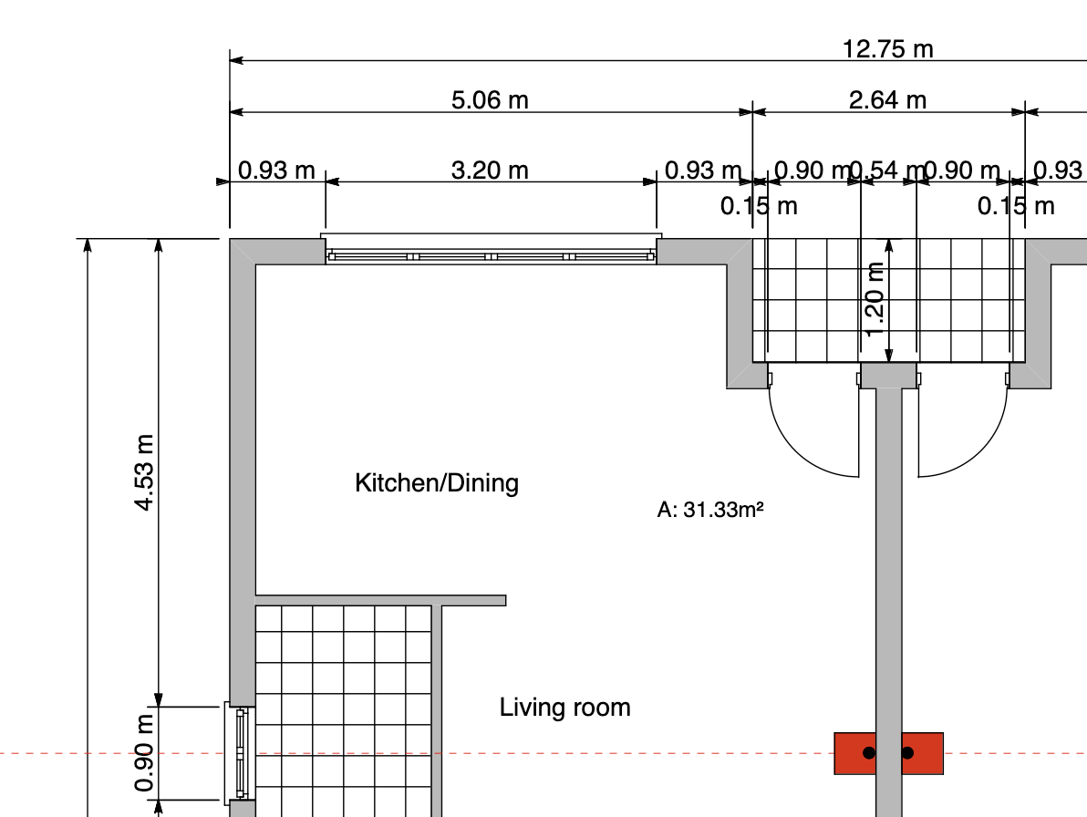
To draw a wall, click to set its start point, move the cursor and click again to set its endpoint: walls are connected like poly-lines. Walls have their construction side and the “Exterior side” property, marked with a blue line, to consider when inserting openings: to change the leading side while drawing, click on the Option menu close to the last vertex. Press the Alt key to invert the exterior side while moving the cursor.
 _
_
A compound wall can be inserted by its structural component: choose between exterior, interior sides and middle line to easily align your walls to the structural grid.
To edit a wall, select it and move, stretch, shorten it with the Arrow tool or change its parameters numerically via the Object Info panel.
Edit a Wall with the Object Info Panel
The Point section of the Object Info panel enables the changes of the coordinates of the three control points of the selected wall: use the arrows to select the active point and the fields to enter the new coordinates.
The Geometry section displays the following options:
- Length and Width fields to change its geometry;
- Leading side buttons to change the construction axis of the wall (this option can shift the selected wall accordingly);
- Invert Sides to invert Interior/Exterior side of the wall (this can invert the opening direction of windows and doors inserted in the selected wall).
The ID section shows the wall Name, Tag and Description fields to add information to the selected wall and provides the Settings button to open the Wall Settings window.
The Tools menu and the contextual menu provide two commands specific for walls: Convert to Wall and Rebuild Wall.
Standard-Case Walls
Standard-case walls have one uniform component and its representation can be a solid color fill, a hatch, or a combination of the two. The geometry can be rectangular, with a constant thickness from start to end point, or polygonal, with variable thickness from start to end.
_
Basic walls automatically join to other basic walls, regardless of thickness and fill, unless the joints are disabled in the Settings window.
Standard-Case Wall Settings Window
- Type pop-up window and New Type icon.
- Family, Basic or Compound
- Geometry and Thickness, in the current unit: selecting the option of variable thickness enables the end thickness field.
- Leading side and Exterior side: select the construction side of the wall. You can also access this option by clicking the pop-up menu icon during the construction the wall. The option to invert the interior and exterior faces of the wall allows to switch the sides of the wall. The exterior side is highlighted in blue when drawing and selecting walls. Wall Joints options. Deselect an option to disable the automatic connection of new walls or to unlink an existing wall.
- Border attributes: Line type and pen weight.
- Fill attributes: solid color, hatch type and color, hatch scale.
Utilities for Walls
Convert to Wall
Convert To Wall applies to lines, polygons, arcs and curves. This function converts those objects into walls with the current settings: select the items to convert and then choose Tools ▸ Walls ▸ Convert To Wall on the Tools menu. This command is also available as a button in the Edit Tool Bar.
Rebuild Wall
Use this command to regenerate the geometry, side intersections and nodes of one or more walls. This is especially useful in situations in which a node needs to fixed.
The Rebuild Wall tool can either be applied to selected walls, or to multiple walls in one run by clicking on them.
To use it on the selection:
- Select the walls you want to rebuild;
- Choose Tools ▸ Rebuild Wall or open the radial menu and choose Rebuild Wall fromthe Tools submenu.
To apply it to multiple walls:
- Choose Tools ▸ Rebuild Wall or open the radial menu and choose Rebuild Wall from the Tools submenu.
- Click once on each wall to rebuild
- Click on a void part or on another object to end.
Wall Tool Settings
Walls are parametric elements of the building that can have several different properties such as sizes, options, functions and compositions that define a wall type. Use the Wall tool settings window to define the parameters of the wall type.
_
Wall Family
You can select to create a standard-case (basic) wall or a composite wall.
Standard-case Walls
When you select standard-case walls, you can select its geometry as regular or irregular. Regular walls are defined by one thickness value and their shape in plan view is rectangular.
Irregular walls are defined by start and end thickness values.
Basic walls automatically join to other basic walls, regardless of thickness and fill, unless the joints are disabled in the Settings window.
Composite Walls
Composite walls consist of multiple layered components, each with its own properties. Composite walls can only be rectangular in shape, with constant thickness from start to end. The total thickness is calculated as the sum of all the internal components.
_
When you select the Composite Wall family in the Settings panel, the family-specific section shows a button to edit the internal components, the value of the total thickness calculated as the sum of the internal components, and the pen wight menu to define the pen to be used for the lines that separate the internal components.
- Composite walls can have any number of internal components, and you can add, remove, reorder and edit the components at any time through the Wall Components window.
- By default, basic walls and compound walls do not join automatically, because they are different elements that would not be joined in a real situation. Also, they are made of different materials which would not match. However, if a particular situation requires it, you can choose to activate the Allow Joints options and attempt to join two walls of different type.
_
Editing Composite Wall Components
Press the Edit button on the Wall tool settings window to open the Wall Components panel. This panel allows you to define, reorder and edit the internal components of the current wall type.
_
The table lists the components of the wall from the exterior side to the interior, with a progressive index number. The selected component is highlighted in the preview, which shows the current wall at the scale. You can check how the wall is rendered at the different drawing scales by using the drawing scale menu on the preview area.
The total thickness of the wall is computed on the sum of the single components and shown at the bottom of the Thickness column.
You can add, remove and reorder the components, and rename a component by double-clicking its name. Use the + button to add a new component and the - button to remove the selected component in the table. Adding a new component opens immediately the properties editor. To edit a component, click the Edit icon on the right.
 _
_
Use Component panel to enter the component name, function, thickness and the hatch to be used in horizontal and vertical sections.
Click the Cancel ✖ or OK ✔ buttons to cancel or confirm the changes to a component and return to the list of components. You can also push the + button to confirm the current component and create a new one directly without going back to the components list.